Exercising the DeskPi PicoMate - Pico 2040 kit
The PicoMate is a well-thought-out experimenter's kit that provides 11 devices that can be attached and used by a Raspberry Pico 2040. It is a breadboard / clip-apart type of configuration. The sensors and outputs come attached to the Pico as part of a snap-apart experimenter board. You can use the board as-is or break off the sensors and emitters and use them connected via JST cables.
They normally cost $40-$60. I found mine for $15 on closeout at Microcenter. I should have bought more.
This rest of this page is more of a Reference and less of User Guide
The PicoMate
The PicoMate includes these devices and features.
- All modules are pre-wired, no soldering and wiring are required and out-of-box
- 12 detachable and easy-to-use modules:
- Push Button
- WS2812 RGB LED
- Rotary Encoder
- Buzzer
- Digital Microphone (ZTS6531S)
- Digital PIR Sensor (AS312)
- 6-Axis IMU Sensor (LSM6DS3TR-C)
- Digital Optical Sensor (LTR-381RGB-01)
- 3-Axis Magnetometer (MMC5603NJ)
- Temperature & Humidity Sensor (SHT30-DIS)
- 0.96” 128x64 OLED Display (SSD1315)
- 204 Pins Breakout Board
- All Pico GPIOs are available via headers and up to 11 Grove connectors are available
- Built-in battery connector for on-the-go projects
- CircuitPython Support
- 3.3V IO operating voltage
Wiring for the peripherals
The peripherals can be used or connected in three main ways.
- All of the peripheral components are connected to the Pico via the small bridges you see in the picture. No wiring is required.
- The individual sensors and output devices can be clipped from the main PCB by cutting the tiny bridges. Then you can use the modular connectors and the provided wires. You can see the connectors in the image below. Some are just direct wired to pins. Others are part of an i2c device chain.
- The individual sensors and output devices can be clipped from the main PCB by cutting the tiny bridges. Then you can solder either headers or wires to the connectors along the edges of the sensor/peripheral boards. You can see the holes in the image below.
Circuit Python Code
All the DeskPi PicoMate sensors are supported in the Adafruit Circuit Python libraries except for the LTR-381RGB-01 light sensor. I couldn't find Python libraries anywhere util I figured out there was one included in the DeskPi library download package. Deskpi provides the driver for that component as a download from their site. I've included it in my GitHub project. The CircuitPython code in my DeskPi-PicoMate GitHub repository was derived from the DeskPi wiki examples
The User Manual snapshots are difficult to read. Use the DeskPi Wiki version that is much clearer.
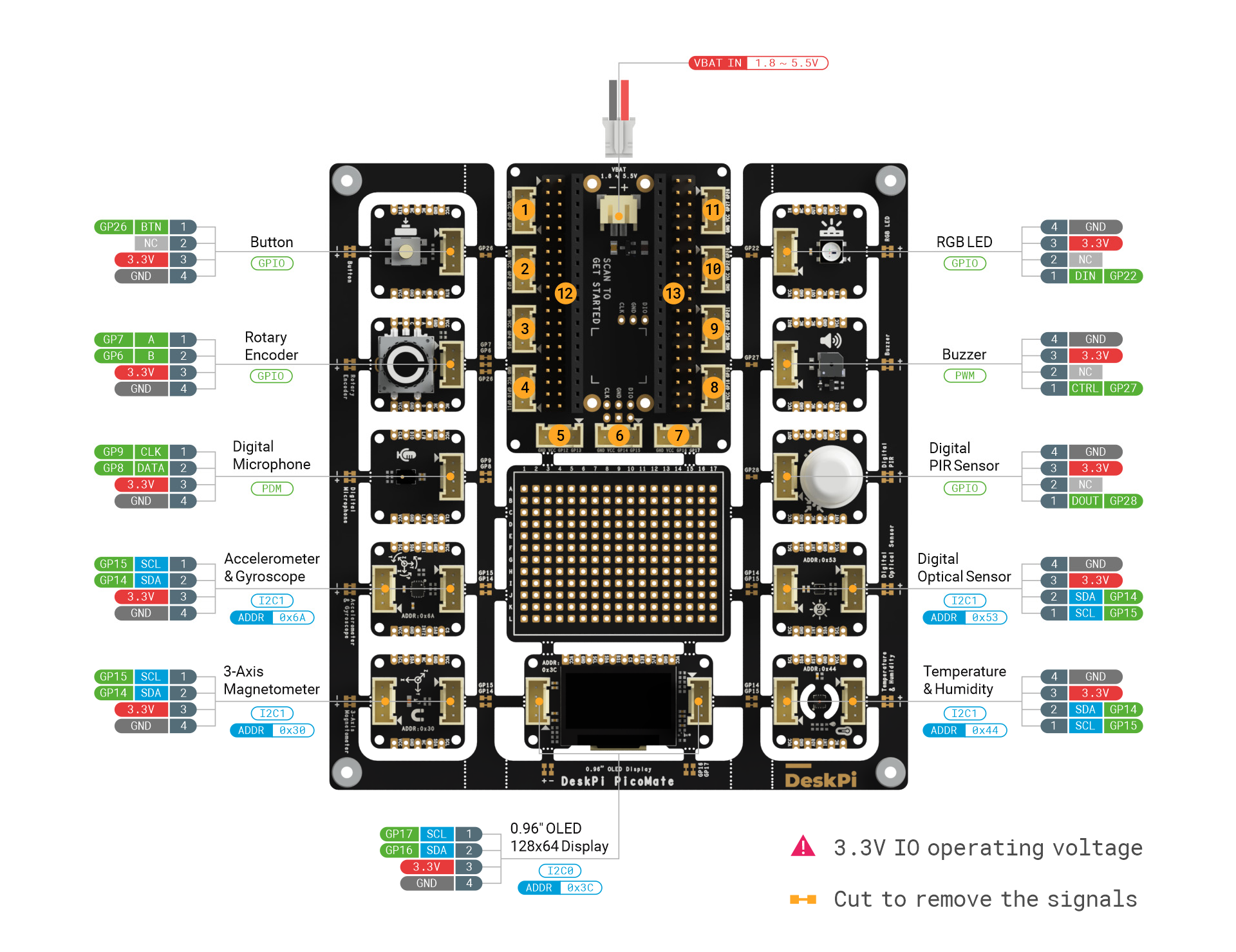
Pinouts
The image below is part of the DeskPi documentation on their Wiki.
DeskPi References
- DeskPi PicoMate User Manual. Use the wiki instead of the manual
- DeskPi PicoMate Wiki
- Library Downloads Us this only for ltr381rgb.py Use the latest CircuitPython package for everything else
- PicoMate Pinout Diagram
- An interesting Printable model for bottom panel
Revision History
- Created 2025 02


Comments
Post a Comment