Installing a serial port connector on the Chumby/Infocast
Overview
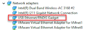
Both the Infocast 8" NS-DP8CH and the Infocast 3.5" NS-DP3CH have 3.3v TTL level serial ports available on connector ports on the motherboards. The serial ports come with transmit (TX), receive (rx) and ground connections and are enabled by default by the Chumby operating system as the boot log on startup and as a serial based terminal after boot. Traditional computer serial ports operate at different voltages and modern computers often have no serial ports at all. Developers and users can connect to the Chumby through the use of a USB to 3.3v serial device adapter cables. Pre-made ftdi brand cables are available on the internet but a lot of folks hack up cheap or surplus USB-cell phone cables like the Nokia. The Chumby is a 3.3v system so don't use a 5v cable. Search on the internet for appropriate cables. USB to serial cables appear to operating systems as (virtual) COM ports. Mine shows up as COM4 on my Windows 7 machine. Many terminal emulators communicate with the device over the virtual serial port as if it was a true serial port simplifying configuration when communicating with the device. I use Putty on my Windows 7 machine.
I like to bring the serial port out of the case with a stereo socket connector. This lets us communicate with the device through the jack without opening up the Chumby. Stereo jacks have 3 wires which matches up with our TX, RX and Ground needs. FTDI sells a USB to stereo jack cable but I make my own following their pinout. TX is on the tip, followed by RX on the 2nd ring and ground closest to the plug. The wires are TX<-->RX RX<-->TX and ground<-->ground. So the stereo socket mounted on the side of the box will connect the Chumby's RX to the tip, TX to the middle ring and ground to the ground ring. The basic steps are.
Infocast 8"

Here's the finished product.

Infocast 3.5"
The 3.5" infocast comes with two unpopulated connectors. The serial. port is in the corner right next to the power button. The following picture shows a right angle connector. The idea here was that a small slit could be cut in the back of the unit next to the power button and that an external connector could be pushed into the unit and on to the pins.
An alternative is to use a straight through header and then create a short stereo jack to header adapter cable. The jack can be mounted anywhere there is room.

The following picture shows the 4 pin serial port connector in the bottom left corner. The 3.3v power pin has been cut because it was not needed and it simplifies figuring out the orientation of the header style connector from a USB/TTL serial cable.

Here you can see that the connector has been replaced with a straight connector. I made up a 3 pin cable with a 4 pin header connector. Just the TX, RX and Ground pins have been connected. The gray plastic under the RYB cable is the rotary encoder used for volume control. We will use the empty space behind that for the stereo jack that will be mounted to the case.

The three wires are connected to the serial headphone jack purchased at Radio Shack. We connect the RX pin on the tip, the TX pin on the middle and the ground on the ring closest to the base. This will connect the USB serial cable's TX (on the tip) to the Chumby RX and the USB cable's RX (2nd ring) to the Chumby TX. You could mount the connector on the back of the unit but liked putting it on the side of the box far enough back that it will not interfere with the rotary encoder on that side.


Both the Infocast 8" NS-DP8CH and the Infocast 3.5" NS-DP3CH have 3.3v TTL level serial ports available on connector ports on the motherboards. The serial ports come with transmit (TX), receive (rx) and ground connections and are enabled by default by the Chumby operating system as the boot log on startup and as a serial based terminal after boot. Traditional computer serial ports operate at different voltages and modern computers often have no serial ports at all. Developers and users can connect to the Chumby through the use of a USB to 3.3v serial device adapter cables. Pre-made ftdi brand cables are available on the internet but a lot of folks hack up cheap or surplus USB-cell phone cables like the Nokia. The Chumby is a 3.3v system so don't use a 5v cable. Search on the internet for appropriate cables. USB to serial cables appear to operating systems as (virtual) COM ports. Mine shows up as COM4 on my Windows 7 machine. Many terminal emulators communicate with the device over the virtual serial port as if it was a true serial port simplifying configuration when communicating with the device. I use Putty on my Windows 7 machine.
I like to bring the serial port out of the case with a stereo socket connector. This lets us communicate with the device through the jack without opening up the Chumby. Stereo jacks have 3 wires which matches up with our TX, RX and Ground needs. FTDI sells a USB to stereo jack cable but I make my own following their pinout. TX is on the tip, followed by RX on the 2nd ring and ground closest to the plug. The wires are TX<-->RX RX<-->TX and ground<-->ground. So the stereo socket mounted on the side of the box will connect the Chumby's RX to the tip, TX to the middle ring and ground to the ground ring. The basic steps are.
Infocast 8"
- Prepare or modify your USB-to-ttl cable. It should be a bus powered cable where the power comes fro the PCGo to radio shack and buy a stereo socket. I shredded an old ISA card for its audio out jacks.
- Open up the Infocast. On the 8", there are 4 screws on the bottom under the rubber feet. There are also two locks in the center of the base on the long sides. I just pried until they popped off but there may be some special way to take off the bottom. The 3.5" exposes 4 screws when looking at the device from the back. Unscrew the 4 motherboard screws and cautiously remove all the connectors. Note that you will have to remove the LCD cable from its' connector on the motherboard. Pry the grey bar up to release the cable. This picture shows the motherboard with a detached LCD cable
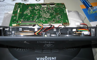
- Find the serial connector on the motherboard at the bottom left as pictured below. Note that the heat shield leaves all the interesting ports exposed. The following pictures shows an open Infocast 8" from the bottom. The unit is face down on the table.

- Solder wires to the TX, RX, GND connectors on the serial port connection points. I like colored cables because it makes easier to figure out what I'm doing I put a little dab of hot clue on my to holder it to the board as a strain relief.
- Solder the TX, RX and GND wires stereo jack making sure that you put the Infocast on the TX on the middle ring and the RX to the tip. The picture below shows the 3 wire connection to the serial port connector (right under the flash glare) This board also has two additional cables attached. The grey cable is connected to the ground and the 4 GPIO pins and has a 5 pin female header socket at the end. The colored wires are connected to the two i2c lines, ground and the 3.3v power pin and have a 4 pin female header socket at the end. This cable's ground line is tied to an unused USB grounding point so that I didn't have to try and solder two wires to the single ground point on the 8 pin port.

- Mount the stereo jack in the side of the Infocast (shown facing down). The empty space next to the motherboard provides ample room for one or more stereo connectors. Youi might be able to barely pick out the grey GPIO cable mentioned above. It and the i2c cables are just left with the connectors on when the unit is sealed up. That lets me use those lines later without having to take the whole unit apart and start soldering

Here's the finished product.

Infocast 3.5"
The 3.5" infocast comes with two unpopulated connectors. The serial. port is in the corner right next to the power button. The following picture shows a right angle connector. The idea here was that a small slit could be cut in the back of the unit next to the power button and that an external connector could be pushed into the unit and on to the pins.
An alternative is to use a straight through header and then create a short stereo jack to header adapter cable. The jack can be mounted anywhere there is room.
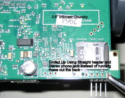
The following picture shows the 4 pin serial port connector in the bottom left corner. The 3.3v power pin has been cut because it was not needed and it simplifies figuring out the orientation of the header style connector from a USB/TTL serial cable.
Here you can see that the connector has been replaced with a straight connector. I made up a 3 pin cable with a 4 pin header connector. Just the TX, RX and Ground pins have been connected. The gray plastic under the RYB cable is the rotary encoder used for volume control. We will use the empty space behind that for the stereo jack that will be mounted to the case.

The three wires are connected to the serial headphone jack purchased at Radio Shack. We connect the RX pin on the tip, the TX pin on the middle and the ground on the ring closest to the base. This will connect the USB serial cable's TX (on the tip) to the Chumby RX and the USB cable's RX (2nd ring) to the Chumby TX. You could mount the connector on the back of the unit but liked putting it on the side of the box far enough back that it will not interfere with the rotary encoder on that side.
Here's the 3.5" unit all buttoned up with the console port installed and labeled.

Wrap Up
Exposing the internal serial port provides a way of communicating with the Infocast machines without enabling SSH. You just plug in your USB/TTL serial cable and fire up your terminal emulator. The TX and RX pins can be converted to PWM lines with a few regutil commands. You can then use the installed stereo connector as a way of bring out those pwm signals.
The Chumby will also bring up a terminal on the device if you plug in a USB keyboard. The downside of this approach is that it ties up the chumby screen while you are exploring.


Comments
Post a Comment