Posts

Showing posts from February, 2023

Two PCIe slots looked the same but gave different benchmark results - PCIe-2 vs PCIe-3

Image
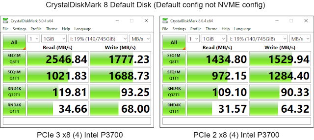
I benchmarked a new-old Intel P3700 PCIe disk drive I got off eBay in my HP Z820 and the P3700 seemed to underperform. I didn't get the performance I expected in a benchmark.  I put the P37000 in the wrong PCIe slot.  The HP Z820 machine has a bunch of PCIe-3, apparently one PCIe-2, and one classic  PCI slot. All the connectors looked the same in the dark but one is not like the others. The P3700 was in the wrong slot. PCIe 3.0 supports a max speed of 8.0 GT/s while PCIe 2.0 supports a max speed of 5.0 GT/s. I have no idea if there was any real-world difference. PCIe 2.0 vs PCIe 3.0 These are two representative samples with an Intel P3700 in the v2 vs v3 slot.  I ran both CrystalDiskMark tests with the Default  setting not the more stressful NVMe configuration. There is a pretty significant boost in sequential performance moving from PCIe-2 to PCIe-3.  The rest of the settings appear to be maxed out because the Default   configuration doesn't generate enough load for an SSD o

Controlling output using Adafruit Logger in CircuitPython

Image
Print statements are the standard debugging and tracing tool for programs running on microcontrollers in non-real-time sections of code. Print statements are a great tool to generate basic output as long as you always  want the output and always  want the output to go to a serial port.   Use the logger if you want to be able to turn print statements on and off without having to continually re-comment and de-comment them. The Adafruit logging library lets you throttle your log output reducing the amount generated. It lets categorize your logging criticality with levels like DEBUG, INFO, WARN, ERROR, etc.  The logger then lets you set the minimum level of criticality for messages to actually be emitted.  If you set your filter level at WARN then no DEBUG or INFO messages show up in the logs/console. This can speed up an application and reduce resource usage while retaining the ability to enable more information if you need it.  The logging library also lets you treat that log output as a

Pendulum Swings in Organizational Design and Execution

Image
Some organizational patterns repeat themselves or alternate between a couple of semi-stable states. Every one of these swings is a reaction to the perceived or actual shortcomings of the previous approach. Centralized vs Federated SME vs All-in-Tech Build a Department vs Destroy a Department Video https://youtu.be/t6V8YKfCALk Slide Content Revision History Created: 2023/02

The Three Envelopes

Image
I heard this years ago while I did contract work at MCI.  We had a project that didn't make a lot of sense and where partner teams joined in case it was successful without any commitment that would risk their other work if it failed. One of the senior people said that our project would never be a failure.  The company would reprioritize and put the software on the shelf for later use. That use would never come.  6 months later that happened. They did the right thing by ignoring the tyranny of sunk cost  but did the wrong thing with the face-saving action plan that wasn't necessary. The Joke ran as follows.  A new executive takes over. On their desk is a box with a note on top. Inside the box are three envelopes. The note says  In case of trouble - Open This   Some Amount of Time Later They start to understand the scope of the challenge They open the First Envelope The note says Blame your predecessor They do this  That buys some time Some Amount of Time Later They see the issu

A power and ground backplane to simplify IoT component connectivity

Image
IoT projects are fun until you move them off the breadboard and then have to solder create reliable connections and power and ground connections.  Some people solder some people use small super-cheap breadboards. I tend to use jumper wires and connectors because most of my stuff is a one-off or super-small batch. It makes rework easy and reliable. The downside is that connectors take up space. The rest of this demonstrates a simple way of making this happen. Video  This discussion on YouTube Schematic Three sets of headers are soldered to a breadboard and joined to each other jin banks. Power (5V) is injected at the jack.  There are power and ground connectors for each device that requires power or ground. Power (5V) and ground lines run from each device and from the jack to the distribution connectors which are plugged into the headers. 3.3 Volt is not on the jack. It is supplied from a voltage regulator on the board and available on its own header row. It is supplied in the schematic

LED Bezels for the Lazy - Print Bezels on Photography Paper and put the NeoPixels behind it

Image
I have no skills when it comes to making nice cabinets. I can't cut, shape, or make anything neat. Everything I build looks like it was done on chemicals with a chainsaw. I wanted to use Neopixels for notifications in my alarm clock hack. Glossy photographic paper can give a finished front but I still have to cut it to let the NeoPixels shine through. It turns out can see light through the Photographic printing paper I have. So I printed the dial and LED frame on the photographic paper and mounted an 8-light Adafruit Neopixel stick behind the paper. The dang things are so bright that the colors are easy to see and it hides all the bad cuts in the case. This is the template I printed on the paper. The Neopixel stick is hot glued into a section of the clock face that was cut out. The square window sits over the LEDs. There are a bunch of markings that I used as guides when laying out the gauge and the NeoPixel window. I just glued the dial printout over the top of the existing Ike

It is hard to not leak PII when redacting screen shots with some editor programs

Image
I ran into a situation recently where I almost leaked some private  data when using a sanitized screenshot. I took a screenshot of an order screen and then marked out all the PII. The programs retain the original image and editing information inside the image so that you can re-edit it later.  This means that anyone else can re-edit unless you protect yourself.  I'm still not sure if I did a transitory upload into some cache before fixing this.  TLDR  Flatten or screenshot any editable PNG files. The latter works for every image. Creating and Using the Image This image started off as a Windows 10 snip  screen capture. I then redacted the private information with black squares.  Later I came back and adjusted the squares to hide data.  I copied the image into a Powerpoint presentation and did a talk.  There was no risk up to this point. My solution I exported the Powerpoint as PNGi mage files.  The image files are flattened images of all the rendered components and are not editable

The difference between Information and Data

Image
Data is a collection of attributes. Information is data that is invested in or drives or has meaning within some type of business or another process.  The same data can represent or have different information contained within the scope of different bounded contexts.  My target here is operational systems where we partition information within business operational contexts. Analytical stores are a bit of a different beast because they tend to be large collections of data that are converted into information through data aggregation and promotion. What is the difference between Information and Data?  Why do we call it Information Science but a Data Lake? I have no idea why they call it the last two but I'm going to use those two labels to bolster my case. Video Slides used in the Video Speaker's notes are to be added at a future date. Revision History Created 2023 02

Trinkey Neo - Updated CircuitPython lights and keys #CircuitPython2023

Image
Did you wish you had a flashier sample CircuitPython capacitive touch program for the Adafruit Trinkey Neo?  That's great because I've got one here.  This upgraded program lets you know that the unit is running and when you've actually touched the capacitive sensor. I started with https://learn.adafruit.com/adafruit-neo-trinkey/capacitive-touch-neopixel-brightness and ended up with the listing below. Video Watch the video to see it in action. Sample Program This Python code is somewhere in this GitHub repository  https://github.com/freemansoft/Adafruit-Trinkey-CircuitPython # SPDX-FileCopyrightText: 2021 Kattni Rembor for Adafruit Industries # # SPDX-License-Identifier: MIT # # updated by freemansoft to include flashing and touch activated colors # originall from https://learn.adafruit.com/adafruit-neo-trinkey/capacitive-touch-hid """CircuitPython Capacitive Touch HID Example for Neo Trinkey""" import time import board import touchi

Belay - Interface with hardware from your PC from within a single Python program

Image
Belay lets you write and run Python code on a host like PC and execute pieces of that code down on a connected microcontroller from inside your host Python session.  You write python code and mark up which code will run on the microcontroller (MCU).  The rest of the code runs on the host.  At runtime Belay will transfer the MCU targeted code down to the microcontroller.  The host Python code can then call that downloaded MCU based code as if it were running locally.  MicroPython CircuitPython and host Python Belay runs on Python3 on the host. It can download and interact with MicroPython or CircuitPython runtimes on the microcontroller. Belay GitHub repository Read the Docs: How Belay works MicroPython CircuitPython Code on both the Host and the Microcontroller Belay Python examples on GitHub All the Python code starts on the PC on the left. For this example, everything is in one file like the led flasher above. Both PC and MCU code is in the same Python source file. We copy any librar

Microcontroller - service connections and acquisition patterns

Image
I ended up with some crosscutting content when I wrote up some patterns for getting data onto and off of microcontrollers. The consumption and generation patterns are cross-matched with implementation details.  You may know where you want to send data or in how many directions you want to send data. Now you have other concerns.  Connecting the devices, triggering transfers, and balancing latency with overhead. The next step is to understand how you are going to handle the connectivity and connection initiation.  That depends on the connection types, network topologies, and tools you have.  You then need to figure out how you are going to know when to capture data or receive commands.  Is it time-based or event-based?   Then you need to understand what your payloads look like and balance that against CPU, latency, and other constraints. This was just a subset but should give you the idea. Related Video Moving IOT data onto the controller Moving IOT data off the controller Microcontrolle