Adding an I2C device to a Chumby
Chumby I2C
The Chumby is a 3.3V device. This means that you have to use 3.3V signal compatible devices. Several of the JeeLabs I2C devices are 3.3V signal compatible. It is possible for some of the 3.3V I2C devices to control higher voltages either through their intrinsic design or through the use of opto-isolators or relays.
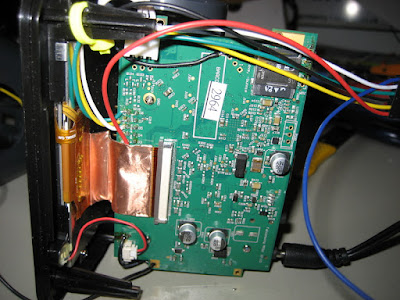
I2C connection pins are available on the Hacker Port on most models. There are some internal devices at certain address so you have to make sure that you don't add additional devices that conflict. I cut one end off of a JeesLabs extension cables and soldered it to the connector. We don't use the IRQ line so it can be removed or taped off to avoid shorts. This is pretty straightforward.
I2C uses 7 bit addressing on a bus that does 8 bit transfers. The thrifty I2C folks make use of the extra bit as a R/W bit. They standardized on the addresses in the upper 7 bits and the R/W bit as the least significant bit. This means that the address is shifted up one bit when calculating addresses in programs. Chumby forum postings indicated that devices exist at:
Device addresses are programmed as x2 addresses. A JeeLabs dimmer at 0x40 (64) is programmed as address 0x80 (128). The programming libraries could have abstracted this away but it don't. Everyone should just get used to the idea of this one bit shift. You will see this in the programming examples below.
I2C controllers normally require a 4 wire connection, power, ground, SDA and SCL. Some I2C devices may provide power to devices on their ports. This means some controllers have an extra pin for alternate voltages. This is also useful when attempting to isolate the external device power bus from the I2C control bus power.
JeeLabs I2C Devices
JeeLabs has their own pin naming convention that they use for I2C and non-I2C devices so you have to map them to normal I2C pin names when connecting to the Chumby.
Programming I2C
The folks at ladyada have a great wiki on the Chumby hacker board which is a Falconwing design very similar to the Infocast 3.5" used for this project. They have a sample program similar to regutil that lets you interrogate and update any i2c device from the command line. Source and compilation instructions for i2c.c are available at http://www.ladyada.net/learn/chumby/i2c.html

JeeLabs Dimmer Plug
The JeeLabs dimmer board is a 3.3v compatible I2C device that has 16 independently controllable PWM ports through the use of an NXP PCA9635 chip. This is a really nice board with pass through connectors for daisy chaining boards and with changeable address jumpers to support multiple boards on the bus. JeeLabs provides an Aruino compatible ports library to simplify talking to their devices. I used their demo program as a basis for my example shell script.
The demo setup ran an LED under dimmer control. The LED was connected from the PWR pin to one of the PWM pins. I connected PWR to a 5V pin on the Chumby to provide higher voltages to my LED strings. We can always use PWM to dim them down later without wasting juice on big resistors.

Example Program for Dimmer Plug
I wrote a shell script that demonstrates how to use that i2c program to exercise the JeesLabs dimmer unit. The following script configures the device and flashes an LED connected to PWM0. An LED is connected to the PWR pin and PWM0 pin with the assumption that PWM0 will sink current from the PWR pin. You can download DimmerDemo.bash
You can create custom C code that provides a device specific UI based on the i2c example program. The folks at ladyada.net did that for the Chumby-One/Hacker boards that include an accelerometer. acceld_i2c.c in the Chumby source tree is also a good code example on how to talk I2C from a C program.
JeeLabs Output Plug
The JeeLabs output board is a 3.3v compatible I2C device that has 8 independently controllable output GPIO each of which has a Darlington transistor pair on it to increase the current limit. JeeLabs docs state that each pin can sink 500ma. I/O is controlled by a Microchip MCP23008T chip. This is a really nice board with pass through connectors for daisy chaining boards and with changeable address jumpers to support multiple boards on the bus. JeeLabs provides an Aruino compatible ports library to simplify talking to their devices. I used their demo program as a basis for my example shell script.
The demo setup ran an LED under output plug control. The LED was connected from the 3.3v pin to one of the IO pins. Real world applications would either use the PWR connection or an external power source. The "common" pin was tied to 3.3v. It acts as the reference voltage for a diode in the driver chip.
Example Program for Output Plug
I wrote a shell script that demonstrates how to use that i2c program to exercise the JeesLabs Output Plug. The following script configures the device and toggles all of the putput pins flashing any connected LEDs. An LED was connected from a power source (3.3v) to one of the I/O pins. Download OutputPlugDemo.bash to see this example
JeeLabs Expander Plug
The JeeLabs Expander board is a 3.3v compatible I2C device that has 8 independently controllable GPIO I/O is controlled by the same Microchip MCP23008T used on the I/O board . This is a really nice board with pass through connectors for daisy chaining boards and with changeable address jumpers to support multiple boards on the bus. JeeLabs provides an Aruino compatible ports library to simplify talking to their devices. I used their demo program as a basis for my example shell script.
The demo setup reads the input levels one time per second for 10 seconds. I connected a couple pins to ground and turned on the pull-ups so that i could get a mix of low and high values
Example Program for Expander Plug
I wrote a shell script that demonstrates how to use that i2c program to exercise the JeesLabs Output Plug. Download ExpanderPlugDemo.bash . It configures the device and reads the values from the GPIO pins.
Conclusion
It is really easy to add I2C devices to a Chumby.
The Chumby is a 3.3V device. This means that you have to use 3.3V signal compatible devices. Several of the JeeLabs I2C devices are 3.3V signal compatible. It is possible for some of the 3.3V I2C devices to control higher voltages either through their intrinsic design or through the use of opto-isolators or relays.
I2C connection pins are available on the Hacker Port on most models. There are some internal devices at certain address so you have to make sure that you don't add additional devices that conflict. I cut one end off of a JeesLabs extension cables and soldered it to the connector. We don't use the IRQ line so it can be removed or taped off to avoid shorts. This is pretty straightforward.

I2C uses 7 bit addressing on a bus that does 8 bit transfers. The thrifty I2C folks make use of the extra bit as a R/W bit. They standardized on the addresses in the upper 7 bits and the R/W bit as the least significant bit. This means that the address is shifted up one bit when calculating addresses in programs. Chumby forum postings indicated that devices exist at:
| Address | Device |
|---|---|
| 0x3A | Accelerometer |
| 0x56 | FM Radio |
| 0xA2 | coproessor EEPROM |
| 0xA8 | DCID EEPROM |
| 0xAA | DCID EEPROM |
| 0xAC | DCID EEPROM |
| 0xAE | DCID EEPROM |
Device addresses are programmed as x2 addresses. A JeeLabs dimmer at 0x40 (64) is programmed as address 0x80 (128). The programming libraries could have abstracted this away but it don't. Everyone should just get used to the idea of this one bit shift. You will see this in the programming examples below.
I2C controllers normally require a 4 wire connection, power, ground, SDA and SCL. Some I2C devices may provide power to devices on their ports. This means some controllers have an extra pin for alternate voltages. This is also useful when attempting to isolate the external device power bus from the I2C control bus power.
JeeLabs I2C Devices
JeeLabs has their own pin naming convention that they use for I2C and non-I2C devices so you have to map them to normal I2C pin names when connecting to the Chumby.
Note: I received the "old" cables so the wires in the pictures match the "old" color scheme in the picture above. The JeeLabs PWR and +3V pins can be independent of each other. The +3V is used to power the chip and the PWR pin is used to provide power to the devices being controlled.
JeeLabs pin Chumby pin JeeLabs color PWR 3.3v or 5v RED DIO SDA YELLOW GND Gnd GREEN (new) BLACK (old) +3V 3.3v BLUE (new) GREEN (old) AIO SCL WHITE IRQ N/C BLACK (new) BLUE (old)
Programming I2C
The folks at ladyada have a great wiki on the Chumby hacker board which is a Falconwing design very similar to the Infocast 3.5" used for this project. They have a sample program similar to regutil that lets you interrogate and update any i2c device from the command line. Source and compilation instructions for i2c.c are available at http://www.ladyada.net/learn/chumby/i2c.html

JeeLabs Dimmer Plug
The JeeLabs dimmer board is a 3.3v compatible I2C device that has 16 independently controllable PWM ports through the use of an NXP PCA9635 chip. This is a really nice board with pass through connectors for daisy chaining boards and with changeable address jumpers to support multiple boards on the bus. JeeLabs provides an Aruino compatible ports library to simplify talking to their devices. I used their demo program as a basis for my example shell script.
The demo setup ran an LED under dimmer control. The LED was connected from the PWR pin to one of the PWM pins. I connected PWR to a 5V pin on the Chumby to provide higher voltages to my LED strings. We can always use PWM to dim them down later without wasting juice on big resistors.

Example Program for Dimmer Plug
I wrote a shell script that demonstrates how to use that i2c program to exercise the JeesLabs dimmer unit. The following script configures the device and flashes an LED connected to PWM0. An LED is connected to the PWR pin and PWM0 pin with the assumption that PWM0 will sink current from the PWR pin. You can download DimmerDemo.bash
You can create custom C code that provides a device specific UI based on the i2c example program. The folks at ladyada.net did that for the Chumby-One/Hacker boards that include an accelerometer. acceld_i2c.c in the Chumby source tree is also a good code example on how to talk I2C from a C program.
JeeLabs Output Plug
The JeeLabs output board is a 3.3v compatible I2C device that has 8 independently controllable output GPIO each of which has a Darlington transistor pair on it to increase the current limit. JeeLabs docs state that each pin can sink 500ma. I/O is controlled by a Microchip MCP23008T chip. This is a really nice board with pass through connectors for daisy chaining boards and with changeable address jumpers to support multiple boards on the bus. JeeLabs provides an Aruino compatible ports library to simplify talking to their devices. I used their demo program as a basis for my example shell script.
The demo setup ran an LED under output plug control. The LED was connected from the 3.3v pin to one of the IO pins. Real world applications would either use the PWR connection or an external power source. The "common" pin was tied to 3.3v. It acts as the reference voltage for a diode in the driver chip.
Example Program for Output Plug
I wrote a shell script that demonstrates how to use that i2c program to exercise the JeesLabs Output Plug. The following script configures the device and toggles all of the putput pins flashing any connected LEDs. An LED was connected from a power source (3.3v) to one of the I/O pins. Download OutputPlugDemo.bash to see this example
JeeLabs Expander Plug
The JeeLabs Expander board is a 3.3v compatible I2C device that has 8 independently controllable GPIO I/O is controlled by the same Microchip MCP23008T used on the I/O board . This is a really nice board with pass through connectors for daisy chaining boards and with changeable address jumpers to support multiple boards on the bus. JeeLabs provides an Aruino compatible ports library to simplify talking to their devices. I used their demo program as a basis for my example shell script.
The demo setup reads the input levels one time per second for 10 seconds. I connected a couple pins to ground and turned on the pull-ups so that i could get a mix of low and high values
Example Program for Expander Plug
I wrote a shell script that demonstrates how to use that i2c program to exercise the JeesLabs Output Plug. Download ExpanderPlugDemo.bash . It configures the device and reads the values from the GPIO pins.
Conclusion
It is really easy to add I2C devices to a Chumby.


Comments
Post a Comment