Aruino + Servo + Ikea Dekad = Freemometer
 After some group success with the Continuous Integration build lights, I wanted an "extreme feedback" way to graphically show our production traffic either through transaction metrics or through server utilization. People understand gauges and alarms so I wanted to incorporate both of those features into some type of device. The end result is a USB controlled dial gauge with real alarm bells and a single red/green LED status light. The total build cost about $53. It contains a text command console that accepts ASCII strings over the COM port. The command console extends control over the LED, the servo motor and the bell motor to the connected host.
 Hardware Design
 I know how to do the basic electronics but nice packaging has always been a problem. Ikea came to the rescue here with the $7.00 Dekad alarm clock with a metal case and alarm bells with an external hammer. The case is pretty good size was originally made for their wind up clock. It is well made and supports dis-assembly and re-assembly without damage. The space between the face and glass has plenty of room for servo arms and LEDs. Three screws hold the back on. The two legs and two bell posts hold the face-plate into the case. The whole clock mechanism and face comes out as a single piece. The clock face is paper stuck to the plate with double sided tape. The paper is 90mm in diameter and the clock face is 80mm in diameter. I was able to draw a new face plate in Microsoft Visio using the Metric page size.
 You can the remove the clock hands once the face-plate is out of the case. The back of the face plate acts as a mounting board for the components. The clock mechanism is connected to the faceplate with two screws and can be removed. The clock unit fastens two the face-plate with two screws. I removed all of the back of the clock mechanism except for the sizes required for the mounting screws. This left enough room to hot glue the servo into the clock box. I then mounted the clock box back on the face using the two mounting screws.
This shows an OSEPP Arduino Nano, the dial servo mounted in the mechanism box, a simple transistor switch to run the bell and the original bell motor. The Nano was chosen because it runs on 5V, because it is available at my local Microcenter and because it fits in the AA battery compartment. The Nano has a USB connector for communication and power. The blue servo is the 9g servo that comes with one of the Arduino kits. A Red/Green two wire LED in the face is mounted in a hole I made with a leather punch. The LED is available at Microcenter in the case mod section (NTE30112).

 The transistor circuit was built on a small Radio Shack perf-board There are really only 4 signals involved, three on the input side and 3 on the output side with power and ground being common to both. I was able to lay out the components so that the 4 unique signals run parallel to each other. I could have also used the Sparkfun Opto-isolator breakout board. for a low solder count solution. The board has two connectors:
- Inputs: Power, Ground and the signal from pin 7.
- Outputs: Power , n/c,n/c and the transistor side of the motor.

There is a lot of space left in this clock with such a small CPU board and alarm bell driver.
Command Processor
Programs can communicate the with the Freemometer command processor over the Virtual COM port associated with Arduino. The command processor accepts ASCII commands making it easy to test the unit with the Arduino IDE console window or through some other serial port program like putty on Windows PCs. The device communicates at 19200bps. It supports the following commands
- h: help
- ?: help
- bell ring <0..9>: Run one ringer patterns (0:off, 1:continuous)
- bell off: sents the ringer to pattern 0, off
- led red <0..9>: turn on red LED using the pattern (0:off, 1:continuous)
- led green <0..9>: turn on green LED using the pattern (0:off, 1:continuous)
- led off: turn off LED
- servo set <0..100>: move servo maps to maximum range
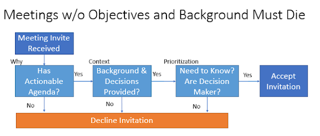
Sample Gauge Faces
Here are some sample gauge faces drawn with Microsoft Visio. The file is in the GitHub repository on a metric scale with US paper sizes.

I'm using the DangerMeter face for a project status gauge with this software on github. Now if I could figure out how to query my TFS backlog...

Source Code
This code uses MsTimer2 to support long term activities like bell timeouts and servo motor motion without having to resort to the delay() function. An MsTimer2 event method moves the servo towards its intended destination by spreading the motion over small steps over some longer period of time. It also tracks the bell pattern and LED flash pattern against the current time, advancing the bell and/or the LED through the pattern as needed. The bell and LED support simple sequences so you can create a variety of patterns to meet different needs or notify of different types of events. There are 10 patterns with 0 as silent and pattern 1 as continuous.
The firmware is available on GitHub and in source form below.
The firmware is available on GitHub and in source form below.
/** * download the MsTimer2 library and put it in your arduino workspace's libraries directory. * The workspace is where all your arduino projects are. You may have to create the libraries directory. * * Written by Joe Freeman joe+arduino@freemansoft.com * http://joe.blog.freemansoft.com/2012/07/aruino-servo-ikea-dekad-freemometer.html * * This is the command firmware fro the Freemometer USB controlled gauge, light and alarm built * on top of the Ikea Dekad retro clock with external hammer bells. Details are on my blog * */ #include <Servo.h> #include <MsTimer2.h> // these two may have to be changed if you swap the connector on the LED // assumes NTE30112 2-wire bi-color LED that can be purchased at Microcenter in casemod section // would also work with 3-wire LED const int PIN_LED_GREEN = 12; // bias green LED connected to digital pin const int PIN_LED_RED = 13; // bias red LED connected to digital pin // servo control pin const int PIN_BELL = 7; // tune to your servo. Mine was 138 degrees with this offset from center. const int SERVO_START_9 = 38; const int SERVO_START_10 = 38; const int SERVO_END_9 = 176; const int SERVO_END_10 = 176; const int SERVO_FULL_RANGE = 100; // Servo library uses Timer1 which means no PWM on pins 9 & 10. // might as well configure both for servos then. // Timer 0 used for millis() and micros() and PWM // Timer 2 available for PWM 8 bit timer or MsTimer2 Servo servo10; Servo servo9; // current position volatile int servoPosition9 = 0; volatile int servoPosition10 = 0; // where we want to be volatile int servoTarget9 = 0; volatile int servoTarget10 = 0; // adjust these two for noise and speed // how many steps per interrupt int servoSpeedPerStep = 4; // in degrees // time between steps int servoStepInterval = 30; // in milliseconds // volatile int bellPattern = 0; // active bell pattern volatile int bellCurrentState = 0; // Current Position in the state array volatile unsigned long bellLastChangeTime; // the 'time' of the last state transition - saves the millis() value // support led patterns using same templates as bells volatile int ledActivePin = PIN_LED_GREEN; volatile int ledPattern = 0; volatile int ledCurrentState = 0; volatile unsigned long ledLastChangeTime; /*================================================================================ * * bell pattern buffer * programming pattern lifted from http://arduino.cc/playground/Code/MultiBlink * *================================================================================*/ typedef struct { boolean isRinging; // digital value for this state to be active (Ring/Silent) unsigned long activeTime; // time to stay active in this state stay in milliseconds } stateDefinition; // the number of pattern steps in every bell pattern const int MAX_RING_STATES = 4; typedef struct { stateDefinition state[MAX_RING_STATES]; // can pick other numbers of slots } ringerTemplate; const int NUM_BELL_PATTERNS = 10; ringerTemplate ringPatterns[] = { // state0 state1 state2 state3 { /* no variable before stateDefinition*/ {{false, 10000}, {false, 10000}, {false, 10000}, {false, 10000}} /* no variable after stateDefinition*/ }, { /* no variable before stateDefinition*/ {{true, 10000}, {true, 10000}, {true, 10000}, {true, 10000}} /* no variable after stateDefinition*/ }, { /* no variable before stateDefinition*/ {{true , 300}, {false, 300}, {false, 300}, {false, 300}} /* no variable after stateDefinition*/ }, { /* no variable before stateDefinition*/ {{false, 300}, {true , 300}, {true , 300}, {true , 300}} /* no variable after stateDefinition*/ }, { /* no variable before stateDefinition*/ {{true , 200}, {false, 100}, {true , 200}, {false, 800}} /* no variable after stateDefinition*/ }, { /* no variable before stateDefinition*/ {{false, 200}, {true , 100}, {false, 200}, {true , 800}} /* no variable after stateDefinition*/ }, { /* no variable before stateDefinition*/ {{true , 300}, {false, 400}, {true , 150}, {false, 400}} /* no variable after stateDefinition*/ }, { /* no variable before stateDefinition*/ {{false, 300}, {true , 400}, {false, 150}, {true , 400}} /* no variable after stateDefinition*/ }, { /* no variable before stateDefinition*/ {{true , 100}, {false, 100}, {true , 100}, {false, 800}} /* no variable after stateDefinition*/ }, { /* no variable before stateDefinition*/ {{false, 100}, {true , 100}, {false, 100}, {true , 800}} /* no variable after stateDefinition*/ }, }; /*================================================================================ * * Start the real code * *================================================================================*/ // The setup() method runs once, when the sketch starts void setup() { // initialize the digital pin as an output: Serial.begin(19200); pinMode(PIN_BELL,OUTPUT); bell_silence(); bellPattern = 0; // active bell pattern bellCurrentState = 0; // Current Position in the state array bellLastChangeTime = millis(); pinMode(PIN_LED_GREEN, OUTPUT); pinMode(PIN_LED_RED, OUTPUT); led_off(); // stat the servo code servo9.attach(9); // attaches the servo on pin 9 to the servo object servo10.attach(10); // attaches the servo on pin 9 to the servo object // put them in the star tposition servoPosition9 = SERVO_START_9; servoPosition10 = SERVO_START_10; // will be on start so set end to be same as start servoTarget9 = servoPosition9; servoTarget10 = servoPosition10; // actually position the servos to their initial position - without delay servo9.write(servoPosition9); servo10.write(servoPosition10); // register function for timer handler at 15ms MsTimer2::set(servoStepInterval, process_servos_and_bell); MsTimer2::start(); delay(200); servo_10_demo(1); //bell_ring_pattern(3); } // main loop that runs as long as Arduino has power void loop() { const int READ_BUFFER_SIZE = 20; char readBuffer[READ_BUFFER_SIZE]; int readCount = 0; char newCharacter = '\0'; while((readCount < READ_BUFFER_SIZE) && newCharacter !='\r'){ if (Serial.available()){ newCharacter = Serial.read(); if (newCharacter != '\r'){ readBuffer[readCount] = newCharacter; readCount++; } } } if (newCharacter == '\r'){ readBuffer[readCount] = '\0'; // got a command so parse it // Serial.print("received "); // Serial.print(readCount); // Serial.print(" characters, command: "); // Serial.println(readBuffer); process_command(readBuffer,readCount); } else { // too many characters so start over } } /*============================================= * make stuff happen *=============================================*/ // this should move to the interrupt handler like the servo code void bell_ring(){ digitalWrite(PIN_BELL,HIGH); // ring bell } // convenience for command void bell_silence(){ digitalWrite(PIN_BELL,LOW); // silence bell } // 0 is the all off pattern. 1 is the all on pattern void bell_ring_pattern(int patternNumber){ bellLastChangeTime = millis(); bellCurrentState=0; bellPattern = patternNumber; check_bell(); } // 0 is the all off pattern. 1 is the all on pattern void led_pattern(int pin, int patternNumber){ ledLastChangeTime = millis(); ledCurrentState=0; ledActivePin = pin; ledPattern = patternNumber; check_led(); } // remember we have a two pin red/green led with no ground so we change color by flipping pins void led_off(){ digitalWrite(PIN_LED_GREEN, LOW); // set the LED on digitalWrite(PIN_LED_RED, LOW); // set the LED off } void led_green(){ digitalWrite(PIN_LED_GREEN, HIGH); // set the LED on digitalWrite(PIN_LED_RED, LOW); // set the LED off } void led_red(){ digitalWrite(PIN_LED_GREEN, LOW); // set the LED off digitalWrite(PIN_LED_RED, HIGH); // set the LED on } void servo_set(int numericParameter){ servo_set_10(numericParameter); } // we just set the target because the intterupt handler actually moves the servo void servo_set_10(int numericParameter){ // do bounds checking? if (numericParameter <= 0){ servoTarget10 = SERVO_START_10; } else if (numericParameter >= SERVO_FULL_RANGE){ servoTarget10 = SERVO_END_10; } else { // calculate percentage of full range int range = SERVO_END_10 - SERVO_START_10; long multiplicand = range * numericParameter; int scaledValue = multiplicand / SERVO_FULL_RANGE; int offsetValue = SERVO_START_10 + scaledValue; servoTarget10 = offsetValue; } } /*============================================= * interrupt handler section *=============================================*/ // Interrupt handler that smoothly moves the servo void process_servos_and_bell(){ move_servo(servo10, "S10", servoPosition10, servoTarget10, SERVO_START_10, SERVO_END_10); move_servo(servo9, "S9", servoPosition9, servoTarget9, SERVO_START_9, SERVO_END_9); check_bell(); check_led(); } // checks the bell pattern void check_bell(){ if (bellPattern >= 0){ // quick range check if (millis() >= bellLastChangeTime + ringPatterns[bellPattern].state[bellCurrentState].activeTime){ // calculate next state with rollover/repeat bellCurrentState = (bellCurrentState+1) % MAX_RING_STATES; bellLastChangeTime = millis(); } // will this cause slight hickups in the bell if it's already ringing or already silent if (ringPatterns[bellPattern].state[bellCurrentState].isRinging){ bell_ring(); } else { bell_silence(); } } } void check_led(){ if (bellPattern >= 0){ // quick range check if (millis() >= ledLastChangeTime + ringPatterns[ledPattern].state[ledCurrentState].activeTime){ // calculate next state with rollover/repeat ledCurrentState = (ledCurrentState+1) % MAX_RING_STATES; ledLastChangeTime = millis(); } // will this cause slight flicker if already showing led? if (ringPatterns[ledPattern].state[ledCurrentState].isRinging){ if (ledActivePin == PIN_LED_GREEN){ led_green(); } else if (ledActivePin == PIN_LED_RED){ led_red(); } else { led_off(); // don't know what to do so just turn off } } else { led_off(); } } } // supports servo movement for multile servos even though prototype only has one void move_servo(Servo servo, String label, volatile int ¤tPosition, volatile int &targetPosition ,int servoMinimum, int servoMaximum){ // only move the servo or process if we're not yet at the target if (currentPosition != targetPosition){ if (currentPosition < targetPosition){ currentPosition+=servoSpeedPerStep; if (currentPosition>targetPosition){ currentPosition = targetPosition; } if (currentPosition>servoMaximum){ currentPosition = servoMaximum; } } if (currentPosition > targetPosition){ currentPosition-=servoSpeedPerStep; if (currentPosition<targetPosition ){ currentPosition = targetPosition; } if (currentPosition<servoMinimum){ currentPosition=servoMinimum; } } servo.write(currentPosition); // Serial.print(label); // Serial.print(":"); // Serial.println(currentPosition); } } /*============================================= * demo code *=============================================*/ // runs a short demo on servo 10 void servo_10_demo(int numberOfDemoCycles){ for (int i = 0 ; i < numberOfDemoCycles; i++){ led_green(); servo_set(SERVO_FULL_RANGE); delay(1000); // wait led_off(); bell_ring(); delay(50); bell_silence(); delay(1000); // wait led_red(); servo_set(0); delay(1000); // wait led_off(); bell_ring(); delay(50); bell_silence(); delay(1000); // wait } } /*================================================================================ * * command handler area * *================================================================================*/ // first look for commands without parameters then with parametes boolean process_command(char *readBuffer,int readCount){ // use string tokenizer to simplify parameters -- could be faster by only running if needed char *command; char *command2; char *parameter; char *parsePointer; // First strtok iteration command = strtok_r(readBuffer," ",&parsePointer); command2 = strtok_r(NULL," ",&parsePointer); parameter = strtok_r(NULL," ",&parsePointer); // optional parameter boolean processedCommand = false; if (readCount == 1){ help(); } else if (strcmp(command,"led") == 0){ if (strcmp(command2,"green")==0){ if (parameter!= NULL){ int numericParameter = atoi(parameter); if (numericParameter < NUM_BELL_PATTERNS && numericParameter >= 0){ led_pattern(PIN_LED_GREEN, numericParameter); processedCommand = true; } } } else if (strcmp(command2,"red")==0){ if (parameter!= NULL){ int numericParameter = atoi(parameter); if (numericParameter < NUM_BELL_PATTERNS && numericParameter >= 0){ led_pattern(PIN_LED_RED, numericParameter); processedCommand = true; } } } else if (strcmp(command2,"off")==0){ led_pattern(PIN_LED_GREEN, 0); // pattern 0 is always off processedCommand = true; } } else if (strcmp(command,"bell") == 0){ if (strcmp(command2,"off")==0){ bell_ring_pattern(0); processedCommand = true; } else if (strcmp(command2,"ring")==0){ if (parameter!= NULL){ int numericParameter = atoi(parameter); if (numericParameter < NUM_BELL_PATTERNS && numericParameter >= 0){ bell_ring_pattern(numericParameter); processedCommand = true; } } } } else if (strcmp(command,"servo")==0){ if (strcmp(command2,"set") == 0){ if (parameter != NULL){ int numericParameter = atoi(parameter); if (numericParameter < 0){ numericParameter = 0; } else if (numericParameter > SERVO_FULL_RANGE) { numericParameter = SERVO_FULL_RANGE; } servo_set(numericParameter); processedCommand = true; } } } else { // completely unrecognized } if (!processedCommand){ Serial.print(command); Serial.println(" not recognized"); } return processedCommand; } void help(){ Serial.println("h: help"); Serial.println("?: help"); Serial.println("bell ring <0..9>: Run one ringer patterns (0:off, 1:continuous)"); Serial.println("bell off: sents the ringer to pattern 0, off"); Serial.println("led red <0..9>: turn on red LED using the pattern (0:off, 1:continuous)"); Serial.println("led green <0..9>: turn on green LED using the pattern (0:off, 1:continuous)"); Serial.println("led off: turn off LED"); Serial.print ("servo set <0..");Serial.print(SERVO_FULL_RANGE);Serial.println(">: move servo maps to maximum range"); Serial.flush(); } // end of file

This comment has been removed by a blog administrator.
ReplyDelete