Digital Thermometer with TI Lanchpad MSP430 and Sparkfun breakout board for Nokia 5110 LCD
 The TI Launchpad comes with a demonstration program that reports the current temperature of the on chip die back to a connected computer over the Launchpad's Serial/USB bridge. The code is written in Texas Instruments Code Composer Studio (CCS). CCS is a nice development environment but assumes a certain level of technical expertise not required when getting started with other environments. The LaunchPad Experimenter's Guide provides a schematic for the board.
The folks on the Energia project on github ( https://github.com/energia/Energia ) project have created a Arduino like development environment for the MSP 430. Their libraries hide the register manipulation details from the developer though knowing those details is important when tuning the power tuning and performance of the MSP 430 CPUs. The Energia project has a sample thermometer program that displays the current temperature on an the Nokia 5110 LCD display. Source is located on their github repository but don't appear in neither the 0101E0006 nor the 0101E0008 installation. The code creates a thermometer that looks like this, with the Nokia 5110 style LCD back-light turned off.
Hardware Configuration
Both the TI Launchpad and the 5110 style LCD run with 3.3v power and signal levels. No level converters are required when connecting them and when powering the LCD's back-light. The LCD has 8 pins including power, ground and the backlight control. This means there are 5 SPI style control pins to be managed by the Launchpad. I used only port 2 to control the LCD. pins_energia.h shows that P2.5 supports analog write so we could do PWM on the back light if we wanted to. Push button 2 is used to control the backlight.
  LCD_5110(P2_4,    // Chip Select *  #3 on sparkfun breakout SCE
           P2_3,    // Serial Clock * #7 on sparkfun breakout SCLK
           P2_2,    // Serial Data *  #6 on sparkfun breakout DN(MOSI)
           P2_1,    // Data/Command * #5 on sparkfun breakout D/C
           P2_0,    // Reset *        #4 on sparkfun breakout RST
           P2_5,    // Backlight      #8 on sparkfun breakout LED
           PUSH2);  // Push Button 2
 The devices is powered using the 3.3 VCC and one of the ground pins on the power connector near the reset button. You can click on the picture to get a bigger view of the connections.
I soldered male headers to the Sparkfun board and the TI Launchpad and then used female/female jumper cables to connect this together. It takes more space than direct solder but lets me rework without risking pads and traces.

I've modified the LCD 5110 demo pogram to report back the temperature to a host computer over the MSP430G2553's hardware UART running at 9600 baud. This is similar to the out-of-the-box TI demo program except that it converts the temp to decimal. The very simple code demonstrates how simple the Arduino environment makes common tasks. My Launchpad boards are version 1.4 which came with earlier CPUs. I upgraded to the later MSP430G2553 CPUs through the TI sample program and updated the board firmware. The only oddity there is the UART pins on the pre-1.5 boards are reversed because TI swapped the RX/TX pins when moving from software UARTs to hardware UARTs. You can see here how I swapped the pins on the header using an old cdrom cable. It just needs some shrink wrap. The code is super simple to support this.
Serial.begin(9600);
// the "display" variable
// contains temp string formatted for LCD
Serial.println(display);
Finding the Source
 A zipped download of the updated software is available. It may go on Github if the project starts to grow.
The firmware updates the LCD and reports over the UART/USB link every 1/2 second. The green LED's brightness indicates the magnitude of the temperature difference between startup and now.
// Red LED=P1.0 which is not on a timer
// see digital_pin_timer[] definition
// Green LED=P1.6 is on T0A1 where pwm is available
// https://github.com/energia/Energia/issues/41
The demo uses software SPI because hardware SPI works on the UART pins which we want to communicate with the computer. The Energia header files say P1.2/P1.6, P2.1/P2.2 and P2.4/P2.5 can support analogWrite(), PWM. The Energia header file says there are only 3 independent analogWrite(), one out of each of the 3 pairs. P1.2 is RX and P1.6 is the on board LED which we will make use of in the program. This leaves the port 4 PWM capable pins for LEDs (2 independent) or servos.
Energia Example Program Modifications
The original source also works for the LCD Shield, which I don't use. The no-argument constructor in LCD_5110.cpp is the code snippet below. This has the advantage of putting PWM on the backlight while leaving one open PWM on P2.5.LCD_5110::LCD_5110() {
LCD_5110(P2_2, // Chip Select
P2_4, // Serial Clock
P2_0, // Serial Data
P2_3, // Data/Command
P1_0, // Reset
P2_1, // Backlight
PUSH2); // Push Button 2
}
The no-arg is called when this line is evaluated on start-up:
LCD_5110 myScreen;
Calling the parameter driven constructor lets us reorder the pins. I didn't really need PWM on the back-light. The following constructor call isolates all of the LCD to port 2 which is kind of slick. It makes for clean cabling but it also ties up 4 out of the 6 pins that support analogWrite() if you wanted to add servos or fancy LEDs.
LCD_5110 myScreen =
LCD_5110(P2_4, // Chip Select * #3 on sparkfun breakout SCE P2_3, // Serial Clock * #7 on sparkfun breakout SCLK P2_2, // Serial Data * #6 on sparkfun breakout DN(MOSI) P2_1, // Data/Command * #5 on sparkfun breakout D/C P2_0, // Reset * #4 on sparkfun breakout RST P2_5, // Backlight #8 on sparkfun breakout LED PUSH2); // Push Button 2
Reordering the pins can free up 2 independent port 2 analogWrite() pins, giving us 3 independent PWM to work with, including P1.6. The following puts sparkfun pins 3,4,5,6 on one side of the Launchpad and 7,8 on the other.
LCD_5110 myScreen =LCD_5110(P1_4, // Chip Select * #3 on sparkfun breakout SCE P2_4, // Serial Clock * #7 on sparkfun breakout SCLK P2_1, // Serial Data * #6 on sparkfun breakout DN(MOSI) P2_0, // Data/Command * #5 on sparkfun breakout D/C P1_5, // Reset * #4 on sparkfun breakout RST P2_3, // Backlight #8 on sparkfun breakout LED PUSH2); // Push Button 2PWM/analogWrite() stays available on pins P2.2 and P2.5, and 1_6 if you give up the magnitude indicator on P1.6.
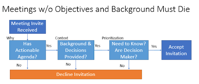
Arduino Style Main Program with UART
The Energia IDE includes the appropriate headers and definitions based on the board type. You Must select the correct "board" type in the Tools-->Board menu. Choose Launchpad w/MSP430g2553. This tells the system the amount of available ROM space, the fact that we have a Hardware UART and configures the IDE for the right registers and other features.
//
//  LCD_5110_main.ino
//  Sketch
//  ----------------------------------
//  Developed with embedXcode
//
//  Project LCD 5110
//  Created by Rei VILO on 28/05/12
//  Copyright (c) 2012 http://embeddedcomputing.weebly.com
//  Licence CC = BY SA NC
//
//  Modified by FreemanSoft to send the current (text) temperature to the hardware serial port @ 9600 baud
//  http://joe.blog.freemansoft.com/2012/08/digital-thermometer-with-ti-lanchpad.html

// Core library
#if defined(__MSP430G2452__) || defined(__MSP430G2553__) || defined(__MSP430G2231__) // LaunchPad specific
#include "Energia.h"
#else
#error Board not supported
#endif

// Include application, user and local libraries
#include "LCD_5110.h"
#include "Thermometer_430.h"

// Variables
//This version isolates to just port 2
/*
  LCD_5110(P2_4,    // Chip Select *  #3 on sparkfun breakout SCE
         P2_3,    // Serial Clock * #7 on sparkfun breakout SCLK
         P2_2,    // Serial Data *  #6 on sparkfun breakout DN(MOSI)
         P2_1,    // Data/Command * #5 on sparkfun breakout D/C
         P2_0,    // Reset *        #4 on sparkfun breakout RST
         P2_5,    // Backlight      #8 on sparkfun breakout LED
         PUSH2);  // Push Button 2
*/
LCD_5110 myScreen =
//This version saves P2_2 and P2_5 as independent PWMLCD_5110(P2_4, // Chip Select * #3 on sparkfun breakout SCE P2_4, // Serial Clock * #7 on sparkfun breakout SCLK P2_1, // Serial Data * #6 on sparkfun breakout DN(MOSI) P2_0, // Data/Command * #5 on sparkfun breakout D/C P1_5, // Reset * #4 on sparkfun breakout RST P2_3, // Backlight #8 on sparkfun breakout LED PUSH2); // Push Button 2Thermometer_430 myThermometer; boolean backlight = false; int ledPinGreen = P1_6; int ledPinRed = P1_0; // Add setup code void setup() { // try and find minimum PWM values myThermometer.begin(); myScreen.begin(); myScreen.setFont(1); myScreen.text(1, 1, "MSP430"); myScreen.setFont(0); myScreen.text(0, 5, "1234567890abcd"); delay(2000); myScreen.clear(); myScreen.text(2, 0, "Thermometer"); myScreen.text(0, 5, "off"); Serial.begin(9600); } // Display mask supports 3 digit + one decimal place char display[8] = {' ', ' ', ' ', '.', ' ', 0x7f, 'C', 0x00}; char displayCalibrationPoint[8] = {' ', ' ', ' ', '.', ' ', 0x7f, 'C', 0x00}; // Add loop code void loop() { if (myScreen.getButton()) { backlight = ~backlight; myScreen.setFont(0); myScreen.text(0, 5, backlight ? "on " : "off"); myScreen.setBacklight(backlight); } myThermometer.get(); // Temperature display int32_t number = myThermometer.temperatureX10(); calculateTemperatureDisplay(display, number); int32_t difference = number- myThermometer.calibrationX10(); // show calculated difference if (difference < 0){ calculateTemperatureDisplay(displayCalibrationPoint, -difference ); } else { calculateTemperatureDisplay(displayCalibrationPoint, difference ); } // show delta in corner myScreen.setFont(0); myScreen.text(7, 5, displayCalibrationPoint); // show the temp in large font myScreen.setFont(1); myScreen.text(0, 2, display); Serial.println(display); displayTemperatureChangeIndicator(difference); delay(500); } void calculateTemperatureDisplay(char *buffer, int32_t number){ boolean flag = (number<0); if (flag) number = -number; buffer[4] = 0x30 + (number%10); number /= 10; buffer[2] = 0x30 + (number%10); number /= 10; if (number>0) { buffer[1] = 0x30 + (number%10); } else if (flag) { buffer[1] = '-'; flag = false; } else { buffer[1] = ' '; } number /= 10; if (number>0) buffer[0] = 0x30 + (number%10); else if (flag) buffer[0] = '-'; else buffer[0] = ' '; } // can't really seem to get the pwm to work right for the RED light // this is because the // red LED is on P1.0 which is not on a timer see digital_pin_timer[] definition // green LED is on P1.6 which is on T0A1 where pwm is available // https://github.com/energia/Energia/issues/41 void displayTemperatureChangeIndicator(int32_t tempChangeX10){ int pinValue; if (tempChangeX10 > 0){ pinValue = tempChangeX10 ; } else { pinValue = -tempChangeX10; } pinValue = pinValue << 3 ; if (pinValue > 255) { pinValue = 255; } // green is the magnitude analogWrite(GREEN_LED,pinValue); }

This reminds me of the time I tried hyper hacking a Nokia 90 communicator to update its firmware. Had to connect it with cables and cat5e for the modem.
ReplyDeleteThanks for a really helpful post. Do you happen to have any recommendations for headers/cables that one can use if one wishes to use the J4 holes for communications between a Launchpad and another board? I've trolled through the web but haven't seen any Check it out simple answers to the question.
ReplyDeleteThe best moment i think when somebody stealing a meat thermometer i really enjoy to read your article and also the digital thermometer make this topic more interesting. thermometers.co.uk
ReplyDeleteOXYPRO Cleaning System is one of the leading brands providing quality, and environmental-friendly Specialty cleaning solutions for laundry, kitchen, housekeeping, food manufacturing, and industrial industries.
ReplyDelete