Web control an addressable LED strip using ArduinoEthernet
Edited 12/18/2011: Added Perl script and made displayColors(); call fix in event handler.
Edited 12/19/2011: Added bulk update POST behavior and updated Perl script to demonstrate.
Edited 12/26/2011: Fixed quoting javascript quoting problem.
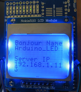
Edited 1/3/2012: Added support for Nokia 5110 style LCD and display bonjour name and IP.
Most of my build and status "blinken light" type projects are USB or Bluetooth (Serial) controlled requiring a direct connection to the machine feeding the project it's values. I wanted more standlone device that could be remotely updated. Microcenter has the ArduinoEthernet and Netduino Plus boards, both of which have onboard ethernet. I still can't get my head around the .Net MF framework and which libraries apply to the Netduino vs some other .Net board. The RaspberryPi is probably the biggest newcomer in this space because of its aggressive pricepoint, large feature set and broader set of developer tools. The Arduinos areprimitive simpler which is what I was looking for here. I purchased the Gheo ArduinoEthernet with its embedded Wiznet W5100 Ethernet chip for $45. This may be a Microcenter price mistake because that is normally the Ethernet shield price on line.
 This is a standalone Arduino Ethernet web Server that accepts POST information that tells it how to control a string of LED lights. It also accepts text and positioning command to display strings on a Nokia 5110 LCD.
This requires a full Ethernet stack, a web server and the ability to do precise serial streams to talk to our 3-wire LED light strip.
I wanted to let the device use the built-in DHCP client for obtaining addresses so that I could use it on any network without a firmware update for static IP. DHCP does make it hard for clients to find the web server since it won't be registered in DNS. I've decided to use Bonjour as a simple network registration protocol so that clients can find the device.

The strip comes with two ground lines, one power line and one signal line. I connected ground to the power source ground and to the Arduino round. I connected the 5V to an off-board power supply so that I wasn't tempted to feed 5v off the Arduino I connected the asynchronous data line to digital pin 8 on my Arduino.

 I've updated the TFS Build Watcher to support this device to show build status using both the LED strip and the optional LED display.
Source code is available on github at https://github.com/freemansoft/build-monitors/tree/master/build-lights-net
Thanks for reading...
Edited 12/19/2011: Added bulk update POST behavior and updated Perl script to demonstrate.
Edited 12/26/2011: Fixed quoting javascript quoting problem.
Edited 1/3/2012: Added support for Nokia 5110 style LCD and display bonjour name and IP.
Most of my build and status "blinken light" type projects are USB or Bluetooth (Serial) controlled requiring a direct connection to the machine feeding the project it's values. I wanted more standlone device that could be remotely updated. Microcenter has the ArduinoEthernet and Netduino Plus boards, both of which have onboard ethernet. I still can't get my head around the .Net MF framework and which libraries apply to the Netduino vs some other .Net board. The RaspberryPi is probably the biggest newcomer in this space because of its aggressive pricepoint, large feature set and broader set of developer tools. The Arduinos are
Project Overview

This requires a full Ethernet stack, a web server and the ability to do precise serial streams to talk to our 3-wire LED light strip.
I wanted to let the device use the built-in DHCP client for obtaining addresses so that I could use it on any network without a firmware update for static IP. DHCP does make it hard for clients to find the web server since it won't be registered in DNS. I've decided to use Bonjour as a simple network registration protocol so that clients can find the device.
Hardware
Arduino pin usage is documented in the source code.
ArduinoEthernet
The ArduinoEthernet http://arduino.cc/en/Main/ArduinoBoardEthernet provides the base platform and Ethernet components. It contains 32KB of program space and an on board Ethernet controller. The W5100 Ethernet controller is described as follows by its creator
The W5100 is a full-featured, single-chip Internet-enabled 10/100 Ethernet controller designed for embedded applications where ease of integration, stability, performance, area and system cost control are required. The W5100 has been designed to facilitate easy implementation of Internet connectivity without OS. The W5100 is IEEE 802.3 10BASE-T and 802.3u 100BASE-TX compliant.
The W5100 includes fully hardwired, market-proven TCP/IP stack and integrated Ethernet MAC & PHY. Hardwired TCP/IP stack supports TCP, UDP, IPv4, ICMP, ARP, IGMP and PPPoE which has been proven in various applications for several years. 16Kbytes internal buffer is included for data transmission. No need of consideration for handling Ethernet Controller, but simple socket programming is required.
Pololu 3-wire 1 Meter Addressable LED Strip
This flexible LED strip uses a clock-less 3-wire interface instead of the more common clocked 4-2 wire interface. The three wires are 5V, GND and Data. The data is essentially an asynchronous serial connection with a little over 2us bit timing. It is like many other serial LED devices in that you have to send all of the data for each LED between the start of the strip and the one at the end of the chain. I generally update the entire strip when making a color change to any LED. Pololu has a lot of data on the project page in addition to source code amples http://www.pololu.com/catalog/product/2540/resources.
The timing window for this device is pretty tight so the Arduino is essentially fully occupied when updating the strip.
The strip comes with two ground lines, one power line and one signal line. I connected ground to the power source ground and to the Arduino round. I connected the 5V to an off-board power supply so that I wasn't tempted to feed 5v off the Arduino I connected the asynchronous data line to digital pin 8 on my Arduino.
Sparkfun FTDI USB to Serial Adapter
The ArduinoEthernet does not come with USB circuitry on-board like an Uno or Leonardo. I used an FTDI serial/USB adapter that came with my ProtoSnap kit.
Nokia 5110 Breakout Board
The Nokia style 5100 LCD display is supports 6 lines of text when using an pixel tall font. I normally use the Sparkfun https://www.sparkfun.com/products/10168 board available at Microcenter. This demonstration uses one I got as part of a "look at the interesting and only partially documented stuff they have on DX" order. The Sparkfun one is prettier and has connectors on both ends. It's mounted here on a proto-shield I got at Microcenter. I powered the unit with 5V but only 3.3 volts to the back light LEDs. The signal lines seem to be able to handle 5V Arduino signals without any signal level adaptation.
Software
The ArduinoEthernet's on board Wiznet adapter handles the hard parts of the ethernet and includes a 16KB TX/RX buffer than lets it capture data while the Arduino is doing something else, like updating the LEDs. The Arduino Ethernet library http://arduino.cc/en/Reference/Ethernet provides TCP/IP connectivity with DHCP address setup. Arduino IDE 1.0.1 comes with these drivers in its library directory.
Webduino Web Server for Arduino
I could have talked over sockets to the ArduinoEthernet but instead decided to put small web server on the device so that any program could push data to the Arduino with a simple HTTP request. I used the Webduino https://github.com/sirleech/Webduino web server library because it really simplifies inbound data with a nice GET/POST processing library. I downloaded this library and copied it into the Arduino IDE library directory.
Bonjour
Bonjour finds a simple way for dynamic IP address programs to find each other almost as if they had static IP addresses that have DNS entries. It is used find and bind printers, network storage and most Apple products. Consumers can use Bonjour to find the Arduino and connect to it without having to hard code its IP address or update DNS.
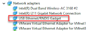
 Anyone can write a program that uses Bonjour services. Information can be found on the Apple developer website. MAC users can see available Bonjour based network services with Safari. Windows users can see available Bonjour services by installing the Windows Bonjour developer kit. It installs an IE browser plugin that shows you Bonjour devices on your network.
 Anyone can write a program that uses Bonjour services. Information can be found on the Apple developer website. MAC users can see available Bonjour based network services with Safari. Windows users can see available Bonjour services by installing the Windows Bonjour developer kit. It installs an IE browser plugin that shows you Bonjour devices on your network.
This library is unnecessary if you use static IP address or if you wish to create a program that talks out, off the Arduino, instead of inbound, to the Arduino.
Pololu LED Strip Library
Sample AVR and Arudino libraries are available on the Pololu LED strip product page . The strip retains its colors so the library only is invoked when colors need to be changed. This is a good thing because the library completely ties up the Arduino when updating the strip.
LED Control Program
I combined a couple programs to create a web server that announces it self with zeroconf. It has a single web page that lets a user change the RGB values of all of the LEDs or a single LED with a single update. The web page has Red, Green and Blue sliders and one LED selecton slider. The client side javascript calls every time a slider position changes with a little bit of time delay to reduce the number of calls that would otherwise be generated by a slider drag action.
The program updates the values on the strip in response to an HTTP POST request. The program registers a handler that reads the POST values and updates the LEDs. The LED slider home position has a value of -1 which causes all of the LEDS to get updated with the current color. Any other position only updates a single LED
The main loop() invokes the Bonjour and WebServer updates the routine so that they can respond to information received over the WizNet component.
The main loop() invokes the Bonjour and WebServer updates the routine so that they can respond to information received over the WizNet component.
Software Constraints
The Bonjour and Web server libraries only leave about 2K of programs space. I combined the Bonjour and Webduino example program along with portions of the Pololu demo program. My simple program doesn't do much which leaves about 1400 bytes left for future programming.
Arduino Firmware
Firmware is available on Github at https://github.com/freemansoft/build-monitor-devices/tree/master/arduino_ethernet_LED
// This file created by joe at freemansoft inc. http://joe.blog.freemansoft.com // This program is written for the Arduino Ethernet http://arduino.cc/en/Main/ArduinoBoardEthernet available at microcenter // Note: // This board uses the following pins // 0 RX when programming/debugging // 1 TX when programming/debugging // 2 W5100 interrupt when bridged // 4 SD Card SS (if not using Nokia 5110) // 3 optional Nokia 5110 CLK // 4 optoinal Nokia 5110 DIn // 5 optoinal Nokia 5110 DC // 6 optoinal Nokia 5110 Rst Reset (6 and 7 are twisted on LCD breakout board) // 7 optoinal Nokia 5110 CE Chip Enable (6 and 7 are twisted on LCD breakout board) // 8 LED Strip // 10 SPI Wiznet SS // 11 SPI // 12 SPI // 13 SPI // It demonstrates how to combine bonjour and the webduino project to create a web // server that controls a TM1803 3-wire LED strip that I acquired from http://www.pololu.com/catalog/product/2541 // The strip used +5V, GND and signal. This program assumes the signal is on 8. // Pololu has written a library available here https://github.com/pololu/pololu-led-strip-arduino // Tie the three grounds together, power supply, strip, arduino ethernet. // // Portions of this file originated from Arduino EthernetBonjour. // The updated code is available here https://github.com/neophob/EthernetBonjour // The original code is available here http://gkaindl.com // // Portions of this file originated from the Webduino project https://github.com/sirleech/Webduino // Portions of this file originated from teh Sparkfun Web site supporting their Nokia LCD breakout board // http://www.sparkfun.com/Code/Nokia_Example_Bitmap.pde // // The web user interface demonstrates the POST API for this service. // // I had code in that logged via serial port but burned too much memory. // // Host API form post can post any number of form elements in a single ost with the following conventions // r=set all RED LEDs to this value // g= set all GREEN LEDs to this value // b= set all BLUDELEDs to this value // r#= set RED LED number '#' to this value // g#= set GREEN LED number '#' to this value // b#= set BLUE LED number '#' to this value // s#= set Nokia 5100 LCD text on line # to this value // c= clear Nokia 5100 LCD value is ignored #if defined(ARDUINO) && ARDUINO > 18 #include #endif // raw arduino ethernet #include // simpleconfig support using bonjour #include #include // TM1803 67us/136us strip #include // mac address make something up. odds of collision on your network are low byte mac[] = { 0x46, 0x52, 0x45, 0x45, 0x4D, 0x4E }; // shortened the name to 12 characters so it fits on the 5110 LCD. // that is not required. You will want to name each device differently #define BONJOUR_HOST_NAME "Arduino_LED" // webduino on top of web server on port 80 // can pick a prefix but I'm not sure how you mention that prefix in the Bonjour library with the text area // this prefix MUST match the URL in the embedded javascript #define PREFIX "/" WebServer webserver(PREFIX, 80); // Create an ledStrip object on pin 8. PololuLedStrip<8> ledStrip; // Create a buffer for holding 60 colors. Takes 90 bytes. #define LED_COUNT 30 rgb_color colors[LED_COUNT]; // don't have space for the adafruit LCD libraries /* * his command is set as the default command for the server. It * handles both GET and POST requests. For a GET, it returns a simple * page with some buttons. For a POST, it saves the value posted to * the red/green/blue variable, affecting the output of the speaker * * this has to go before startup because it is referenced */ void stripCmd(WebServer &server, WebServer::ConnectionType type, char *, bool) { if (type == WebServer::POST) { bool repeat; char name[5]; // we shortened all our post variable names to 3 digits including the LED # char value[36]; char * nameNumber; do { /* readPOSTparam returns false when there are no more parameters * to read from the input. We pass in buffers for it to store * the name and value strings along with the length of those * buffers. */ repeat = server.readPOSTparam(name, 6, value, 32); /* strcmp is a standard string comparison function. It returns 0 * when there's an exact match. We're looking for a parameter * named "r", "g" or "b" here. The character comparison saved 40 bytes * * These must exactly match the javascript post variable names */ /* use the Ascii to Int function to turn the string * version of the color strength value into our unsigned char red/green/blue * variable */ if (name[0] == 'c'){ LCDClear(); } else if (name[0]=='s' && name[1] != '\0'){ nameNumber = &name[1]; int row = atoi(nameNumber); gotoXY(0,row); LCDString(" "); // bug: quick hard coded hack that knows screen width gotoXY(0,row); LCDString(value); } else { // this exists to support the sliders in the web interface // just modify them all int valueAsInt = atoi(value); if (name[0]=='r' && name[1]=='\0') { for (int i = 0; i < LED_COUNT; i ++){ colors[i].red = valueAsInt; } } else if (name[0]=='g' && name[1]=='\0') { for (int i = 0; i < LED_COUNT; i ++){ colors[i].green = valueAsInt; } } else if (name[0]=='b' && name[1]=='\0') { for (int i = 0; i < LED_COUNT; i ++){ colors[i].blue = valueAsInt; } } else { // this is the preferred interface if you want to set lots of lights. // r0,r1,r2,...,g0,g1,g2,...,b0,g1,g2,... nameNumber = &name[1]; int webTarget = atoi(nameNumber); if (name[0] == 'r'){ colors[webTarget].red = valueAsInt; } else if (name[0] == 'g'){ colors[webTarget].green = valueAsInt; } else if (name[0] == 'b'){ colors[webTarget].blue = valueAsInt; } } } } while (repeat); displayColors(); // after procesing the POST data, tell the web browser to reload // the page using a GET method. server.httpSeeOther(PREFIX); return; } /* for a GET or HEAD, send the standard "it's all OK headers" */ server.httpSuccess(); /* we don't output the body for a HEAD request */ if (type == WebServer::GET) { /* store the HTML in program memory using the P macro */ P(message) = "\n" " LED Strip Controller \n" "" "" "\n" "\n" "\n" "\n" "" "" "" "" "\n" "\n"; server.printP(message); } } void setup() { // start the ethernet loop Ethernet.begin(mac); // Initialize the Bonjour/MDNS library. You can now reach or ping this // Arduino via the host name "arduino_LED_strip.local", provided that your operating // system is Bonjour-enabled (such as MacOS X). // Always call this before any other method! // esentially the server name in bonjour EthernetBonjour.begin(BONJOUR_HOST_NAME); // Now let's register the service we're offering (a web service) via Bonjour! // To do so, we call the addServiceRecord() method. The first argument is the // name of our service instance and its type, separated by a dot. In this // case, the service type is _http. There are many other service types, use // google to look up some common ones, but you can also invent your own // service type, like _mycoolservice - As long as your clients know what to // look for, you're good to go. // The second argument is the port on which the service is running. This is // port 80 here, the standard HTTP port. // The last argument is the protocol type of the service, either TCP or UDP. // Of course, our service is a TCP service. // With the service registered, it will show up in a Bonjour-enabled web // browser. As an example, if you are using Apple's Safari, you will now see // the service under Bookmarks -> Bonjour (Provided that you have enabled // Bonjour in the "Bookmarks" preferences in Safari). EthernetBonjour.addServiceRecord("Arduino Adressable LED Strip._http", 80, MDNSServiceTCP); // register default command on the discoverable url http://a.b.c.d/strip_cmd webserver.setDefaultCommand(&stripCmd); // start the webduino processing webserver.begin(); // display the initial set of colors displayColors(); // space padding not required but it reminds me we have 12 characters per line LCDInit(); //Init the LCD LCDClear(); LCDString("Bonjour Name"); gotoXY(0,1); // clear reset to the home position LCDString(BONJOUR_HOST_NAME); gotoXY(0,3); LCDString("Server IP"); gotoXY(0,4); char buf[4]; for (byte thisByte = 0; thisByte < 4; thisByte++) { if (thisByte != 0){ LCDString("."); } // print the value of each byte of the IP address: itoa(Ethernet.localIP()[thisByte],buf,10); LCDString(buf); } } void loop() { // This actually runs the Bonjour module. // YOU HAVE TO CALL THIS PERIODICALLY, OR NOTHING WILL WORK! // Preferably, call it once per loop(). EthernetBonjour.run(); // start the webduino component. // YOU HAVE TO CALL THIS PERIODICALLY, OR NOTHING WILL WORK! // Preferably, call it once per loop(). webserver.processConnection(); // show colors based the current values // no need to do this because the handler does it now //displayColors(); } void displayColors(){ // Write the colors to the LED strip. // could be dupe copy to LEDs if was set to NO_TARGET ledStrip.write(colors, LED_COUNT); } /*********************************************************** 7-17-2011 Spark Fun Electronics 2011 Nathan Seidle This code is public domain but you buy me a beer if you use this and we meet someday (Beerware license). This code writes a series of images and text to the Nokia 5110 84x48 graphic LCD: http://www.sparkfun.com/products/10168 Do not drive the backlight with 5V. It will smoke. However, the backlight on the LCD seems to be happy with direct drive from the 3.3V regulator. Although the PCD8544 controller datasheet recommends 3.3V, the graphic Nokia 5110 LCD can run at 3.3V or 5V. No resistors needed on the signal lines. You will need 5 signal lines to connect to the LCD, 3.3 or 5V for power, 3.3V for LED backlight, and 1 for ground. ***********************************************************/ #define PIN_SCE 7 //Pin 3 on LCD #define PIN_RESET 6 //Pin 4 on LCD #define PIN_DC 5 //Pin 5 on LCD #define PIN_SDIN 4 //Pin 6 on LCD #define PIN_SCLK 3 //Pin 7 on LCD //The DC pin tells the LCD if we are sending a command or data #define LCD_COMMAND 0 #define LCD_DATA 1 //You may find a different size screen, but this one is 84 by 48 pixels #define LCD_X 84 #define LCD_Y 48 //This table contains the hex values that represent pixels //for a font that is 5 pixels wide and 8 pixels high static const byte ASCII[][5] = { {0x00, 0x00, 0x00, 0x00, 0x00} // 20 ,{0x00, 0x00, 0x5f, 0x00, 0x00} // 21 ! ,{0x00, 0x07, 0x00, 0x07, 0x00} // 22 " ,{0x14, 0x7f, 0x14, 0x7f, 0x14} // 23 # ,{0x24, 0x2a, 0x7f, 0x2a, 0x12} // 24 $ ,{0x23, 0x13, 0x08, 0x64, 0x62} // 25 % ,{0x36, 0x49, 0x55, 0x22, 0x50} // 26 & ,{0x00, 0x05, 0x03, 0x00, 0x00} // 27 ' ,{0x00, 0x1c, 0x22, 0x41, 0x00} // 28 ( ,{0x00, 0x41, 0x22, 0x1c, 0x00} // 29 ) ,{0x14, 0x08, 0x3e, 0x08, 0x14} // 2a * ,{0x08, 0x08, 0x3e, 0x08, 0x08} // 2b + ,{0x00, 0x50, 0x30, 0x00, 0x00} // 2c , ,{0x08, 0x08, 0x08, 0x08, 0x08} // 2d - ,{0x00, 0x60, 0x60, 0x00, 0x00} // 2e . ,{0x20, 0x10, 0x08, 0x04, 0x02} // 2f / ,{0x3e, 0x51, 0x49, 0x45, 0x3e} // 30 0 ,{0x00, 0x42, 0x7f, 0x40, 0x00} // 31 1 ,{0x42, 0x61, 0x51, 0x49, 0x46} // 32 2 ,{0x21, 0x41, 0x45, 0x4b, 0x31} // 33 3 ,{0x18, 0x14, 0x12, 0x7f, 0x10} // 34 4 ,{0x27, 0x45, 0x45, 0x45, 0x39} // 35 5 ,{0x3c, 0x4a, 0x49, 0x49, 0x30} // 36 6 ,{0x01, 0x71, 0x09, 0x05, 0x03} // 37 7 ,{0x36, 0x49, 0x49, 0x49, 0x36} // 38 8 ,{0x06, 0x49, 0x49, 0x29, 0x1e} // 39 9 ,{0x00, 0x36, 0x36, 0x00, 0x00} // 3a : ,{0x00, 0x56, 0x36, 0x00, 0x00} // 3b ; ,{0x08, 0x14, 0x22, 0x41, 0x00} // 3c < ,{0x14, 0x14, 0x14, 0x14, 0x14} // 3d = ,{0x00, 0x41, 0x22, 0x14, 0x08} // 3e > ,{0x02, 0x01, 0x51, 0x09, 0x06} // 3f ? ,{0x32, 0x49, 0x79, 0x41, 0x3e} // 40 @ ,{0x7e, 0x11, 0x11, 0x11, 0x7e} // 41 A ,{0x7f, 0x49, 0x49, 0x49, 0x36} // 42 B ,{0x3e, 0x41, 0x41, 0x41, 0x22} // 43 C ,{0x7f, 0x41, 0x41, 0x22, 0x1c} // 44 D ,{0x7f, 0x49, 0x49, 0x49, 0x41} // 45 E ,{0x7f, 0x09, 0x09, 0x09, 0x01} // 46 F ,{0x3e, 0x41, 0x49, 0x49, 0x7a} // 47 G ,{0x7f, 0x08, 0x08, 0x08, 0x7f} // 48 H ,{0x00, 0x41, 0x7f, 0x41, 0x00} // 49 I ,{0x20, 0x40, 0x41, 0x3f, 0x01} // 4a J ,{0x7f, 0x08, 0x14, 0x22, 0x41} // 4b K ,{0x7f, 0x40, 0x40, 0x40, 0x40} // 4c L ,{0x7f, 0x02, 0x0c, 0x02, 0x7f} // 4d M ,{0x7f, 0x04, 0x08, 0x10, 0x7f} // 4e N ,{0x3e, 0x41, 0x41, 0x41, 0x3e} // 4f O ,{0x7f, 0x09, 0x09, 0x09, 0x06} // 50 P ,{0x3e, 0x41, 0x51, 0x21, 0x5e} // 51 Q ,{0x7f, 0x09, 0x19, 0x29, 0x46} // 52 R ,{0x46, 0x49, 0x49, 0x49, 0x31} // 53 S ,{0x01, 0x01, 0x7f, 0x01, 0x01} // 54 T ,{0x3f, 0x40, 0x40, 0x40, 0x3f} // 55 U ,{0x1f, 0x20, 0x40, 0x20, 0x1f} // 56 V ,{0x3f, 0x40, 0x38, 0x40, 0x3f} // 57 W ,{0x63, 0x14, 0x08, 0x14, 0x63} // 58 X ,{0x07, 0x08, 0x70, 0x08, 0x07} // 59 Y ,{0x61, 0x51, 0x49, 0x45, 0x43} // 5a Z ,{0x00, 0x7f, 0x41, 0x41, 0x00} // 5b [ ,{0x02, 0x04, 0x08, 0x10, 0x20} // 5c \\ escape the backslash or a row vanishes ,{0x00, 0x41, 0x41, 0x7f, 0x00} // 5d ] ,{0x04, 0x02, 0x01, 0x02, 0x04} // 5e ^ ,{0x40, 0x40, 0x40, 0x40, 0x40} // 5f _ ,{0x00, 0x01, 0x02, 0x04, 0x00} // 60 ` ,{0x20, 0x54, 0x54, 0x54, 0x78} // 61 a ,{0x7f, 0x48, 0x44, 0x44, 0x38} // 62 b ,{0x38, 0x44, 0x44, 0x44, 0x20} // 63 c ,{0x38, 0x44, 0x44, 0x48, 0x7f} // 64 d ,{0x38, 0x54, 0x54, 0x54, 0x18} // 65 e ,{0x08, 0x7e, 0x09, 0x01, 0x02} // 66 f ,{0x0c, 0x52, 0x52, 0x52, 0x3e} // 67 g ,{0x7f, 0x08, 0x04, 0x04, 0x78} // 68 h ,{0x00, 0x44, 0x7d, 0x40, 0x00} // 69 i ,{0x20, 0x40, 0x44, 0x3d, 0x00} // 6a j ,{0x7f, 0x10, 0x28, 0x44, 0x00} // 6b k ,{0x00, 0x41, 0x7f, 0x40, 0x00} // 6c l ,{0x7c, 0x04, 0x18, 0x04, 0x78} // 6d m ,{0x7c, 0x08, 0x04, 0x04, 0x78} // 6e n ,{0x38, 0x44, 0x44, 0x44, 0x38} // 6f o ,{0x7c, 0x14, 0x14, 0x14, 0x08} // 70 p ,{0x08, 0x14, 0x14, 0x18, 0x7c} // 71 q ,{0x7c, 0x08, 0x04, 0x04, 0x08} // 72 r ,{0x48, 0x54, 0x54, 0x54, 0x20} // 73 s ,{0x04, 0x3f, 0x44, 0x40, 0x20} // 74 t ,{0x3c, 0x40, 0x40, 0x20, 0x7c} // 75 u ,{0x1c, 0x20, 0x40, 0x20, 0x1c} // 76 v ,{0x3c, 0x40, 0x30, 0x40, 0x3c} // 77 w ,{0x44, 0x28, 0x10, 0x28, 0x44} // 78 x ,{0x0c, 0x50, 0x50, 0x50, 0x3c} // 79 y ,{0x44, 0x64, 0x54, 0x4c, 0x44} // 7a z ,{0x00, 0x08, 0x36, 0x41, 0x00} // 7b { ,{0x00, 0x00, 0x7f, 0x00, 0x00} // 7c | ,{0x00, 0x41, 0x36, 0x08, 0x00} // 7d } ,{0x10, 0x08, 0x08, 0x10, 0x08} // 7e ~ ,{0x78, 0x46, 0x41, 0x46, 0x78} // 7f DEL }; void gotoXY(int x, int y) { LCDWrite(0, 0x80 | x); // Column. LCDWrite(0, 0x40 | y); // Row. ? } //This function takes in a character, looks it up in the font table/array //And writes it to the screen //Each character is 8 bits tall and 5 bits wide. We pad one blank column of //pixels on each side of the character for readability. void LCDCharacter(char character) { LCDWrite(LCD_DATA, 0x00); //Blank vertical line padding for (int index = 0 ; index < 5 ; index++) LCDWrite(LCD_DATA, ASCII[character - 0x20][index]); //0x20 is the ASCII character for Space (' '). The font table starts with this character LCDWrite(LCD_DATA, 0x00); //Blank vertical line inter-character padding } //Given a string of characters, one by one is passed to the LCD void LCDString(char *characters) { while (*characters) LCDCharacter(*characters++); } //Clears the LCD by writing zeros to the entire screen void LCDClear(void) { for (int index = 0 ; index < (LCD_X * LCD_Y / 8) ; index++) LCDWrite(LCD_DATA, 0x00); gotoXY(0, 0); //After we clear the display, return to the home position } //This sends the magical commands to the PCD8544 void LCDInit(void) { //Configure control pins pinMode(PIN_SCE, OUTPUT); pinMode(PIN_RESET, OUTPUT); pinMode(PIN_DC, OUTPUT); pinMode(PIN_SDIN, OUTPUT); pinMode(PIN_SCLK, OUTPUT); //Reset the LCD to a known state digitalWrite(PIN_RESET, LOW); digitalWrite(PIN_RESET, HIGH); LCDWrite(LCD_COMMAND, 0x21); //Tell LCD that extended commands follow LCDWrite(LCD_COMMAND, 0xB1); //Set LCD Vop (Contrast): Try 0xB1(good @ 3.3V) or 0xBF if your display is too dark LCDWrite(LCD_COMMAND, 0x04); //Set Temp coefficent LCDWrite(LCD_COMMAND, 0x14); //LCD bias mode 1:48: Try 0x13 or 0x14 LCDWrite(LCD_COMMAND, 0x20); //We must send 0x20 before modifying the display control mode LCDWrite(LCD_COMMAND, 0x0C); //Set display control, normal mode. 0x0D for inverse } //There are two memory banks in the LCD, data/RAM and commands. This //function sets the DC pin high or low depending, and then sends //the data byte void LCDWrite(byte data_or_command, byte data) { digitalWrite(PIN_DC, data_or_command); //Tell the LCD that we are writing either to data or a command //Send the data digitalWrite(PIN_SCE, LOW); shiftOut(PIN_SDIN, PIN_SCLK, MSBFIRST, data); digitalWrite(PIN_SCE, HIGH); }
Driving the Device
The firmware supports two different HTTP POST models.- The single/all LED control as demonstrated by the web interface.
- There are 4 fields, 'r', 'g', 'b' and 'l' where 'l' is the led number. LED = -1 means change all the LEDs to the r/g/b value. LED = 0-29 means change that individual LED to the RGB value.
- An arbitrary number LEDs changed in a single post. This is demonstrated in the PERL program.
- POST parameters are 'r#', 'g#' and 'b#" where the # is the LED number from 0-29. This lets you individually set each channel for each LED. Values not modified in the POST are left as they were.
Sample Perl Code
# cpanm Net::Bonjour not needed  because we know the name
use HTTP::Request::Common;
use LWP;
use Time::HiRes; qw(usleep);

$ua = LWP::UserAgent->new;
#the Bonjour name we gave it in the arduino code
$url = 'http://arduino_led.local/';
$num_leds = 30;
# blank the lights using the "all led" command
$ua->post($url,
 [ r  => '0',
  g => '0',
  b => '0',
  l => '-1',
  c => 'NA'
 ],
);

# now turn all of them on white using the bulk set command
# post accepts array ref or hash ref so lets create a hash ref
print "bam!  do them all in a single call (4 times)\n";
my $post_hash  ;
for ($color=3;$color>=0;$color--) {
 $post_hash{"s5"} = "Updating All";
 $actual_color=$color*64;
 for ($count = 0 ; $count < $num_leds; $count++){
  $post_hash{"r$count"} = $actual_color;
  $post_hash{"g$count"} = $actual_color;
  $post_hash{"b$count"} = $actual_color;
 }
 $ua->post($url,\%post_hash);
}

# turn on the lights one per time using the original single led command
# this is a LOT slower
# examples all use
#  $ua->post($url,
#   [ r  => '0',
#    g => '0',
#    b => $actual_color,
#    l => $three
#   ],
#  );

# demo one led per post
for ($color=3;$color>=0;$color--) {
 $actual_color=$color*64;
 $i = 0;
 while ($i < $num_leds) {
  $one = $i+0;
  $two = $i+1;
  $three = $i+2;
  print "doing $one - $actual_color\n";
  %{$post_hash} = ();
  $post_hash{"s5"} = "Updating $one";
  $post_hash{"r$one"} = $actual_color;
  $post_hash{"g$one"} = '0';
  $post_hash{"b$one"} = '0';
  $ua->post($url,\%post_hash);
  print "doing $two - $actual_color\n";
  %{$post_hash} = ();
  $post_hash{"s5"} = "Updating $two";
  $post_hash{"r$two"} = '0';
  $post_hash{"g$two"} =  $actual_color;
  $post_hash{"b$two"} = '0';
  $ua->post($url,\%post_hash);
  print "doing $three - $actual_color\n";
  %{$post_hash} = ();
  $post_hash{"s5"} = "Updating $three";
  $post_hash{"r$three"} = '0';
  $post_hash{"g$three"} = '0';
  $post_hash{"b$three"} = $actual_color;
  $ua->post($url,\%post_hash);
  $i=$i+3;
 };
}
TFS Build Watcher

Source code is available on github at https://github.com/freemansoft/build-monitors/tree/master/build-lights-net
Thanks for reading...


This comment has been removed by a blog administrator.
ReplyDeleteDid u encounter slow response after sliding the colour bar ?? I turn on serial monitor and found out the analogWrite was slow or not responding after I slide the colour bar... tried on both Chrome and Firefox, same slow speed or at times did not even change the colour at all...
ReplyDeleteI'm using the latest codes from github :-
https://github.com/sirleech/Webduino/tree/master/examples/Web_AjaxRGB
Wow look so good!
ReplyDeleteI'm interest your content !