Combining Arduino Ethernet and Adafruit NeoPixel shield to create web controlled LED goodness
 Someone asked how hard it would be to swap the NeoPixel shield in place of the LED strip in an earlier Arduino based Web LED control project. The Embedded web server and LCD panel control chew up a lot of memory so I wasn't sure there was enough program space for the Adafruit NeoPixel library. It turns out there is just enough space while still retaining some Bonjour functionality. You can get the source code on GitHub
Hardware and Software
This project uses the following hardware

- Arduino Ethernet I picked mine up at Microcenter. They describe this unit as an Ethernet Shield but it is a full Arduino Ethernet for $49 (as of 2014/06). The Arduino IDE supports this board. I used version 1.0.5.
- Adafruit NeoPixel Shield is a 5x8 matrix of individually controllable RGB LED. The software library is available on GitHub.
- A simple protoshield with pass-through connectors. The Ethernet connector is very large and the Neopixel Shield sits right on top of it. I used a prototyping shield to lift the NeoPixel board off the connector. You can see the cutout around the Ethernet connector on the right of the picture. It also gives me an easy place to connect the Nokia 5110 LCD display.
- Nokia 5110 LCD display. Sparkfun makes one with a nice breakout board that is also available at Microcenter. I soldered a connector for it to the protoshield. The LCD is not shown in the picture.
- FTDI USB adapter for programming the Arduino.
 This project uses the following libraries our source. Close any open Arduino IDE windows before installing any libraries. Install the first three libraries in your Arduino libraries directory in ~/Documents/Arduino/libraries. Restart the IDE. The libraries should now show up in the import list. (Ignore MSTimer2 in the picture)
- Adafruit NeoPixel Library on GitHub
- Bonjour compatible zeroconf library on GitHub
- Arduino web server capability, aka Webduino, available on GitHub
- Example 5110 sample code embedded in this project since it was not available as a library when I first pulled it in.
// 0 RX when programming/debugging // 1 TX when programming/debugging // 2 W5100 interrupt when bridged // 4 SD Card SS (if not using Nokia 5110) // 3 optional Nokia 5110 CLK // 4 optional Nokia 5110 DIn // 5 optional Nokia 5110 DC // 6 NeopPixel Sheild (default pin) // 7 optional Nokia 5110 Rst Reset (6 and 7 are twisted on LCD breakout board) // 8 optional Nokia 5110 CE Chip Enable (6 and 7 are twisted on LCD breakout board) // 10 SPI Wiznet SS // 11 SPI // 12 SPI // 13 SPI
Communicating With the Board
Finding the Board
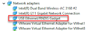
The board uses DHCP to acquire an IP address and registers itself with zeroconf Bonjour under the name http://arduino_neo.local/. This means you can find the device address using DNS-sd on a windows machine.

Verify Function with Web Interface
The program provides a simple test web page to verify network connectivity and simple LED control. It is located at http://arduino_neo.local/. The three RGB sliders set all the lights to the same color based on slider values. They use r=, g= and b=
POST-ing Data
You can change LED colors and brightness by POSTING form data. The system will return 200 if the data appears to be basically correct. It will return 400 if any data is out of range, a nonexistent LED number for instance. The form parameters are as follows:
  // r=<value>  set all RED LEDs to this value

  // g=<value>  set all GREEN LEDs to this value

  // b=<value>  set all BLUDELEDs to this value

  //

  // r#=<value> set RED LED number '#' to this value

  // g#=<value> set GREEN LED number '#' to this value

  // b#=<value> set BLUE LED number '#' to this value

  // s#=<value> set Nokia 5100 LCD text on line # to this value

  // c=<value>  clear Nokia 5100 LCD value is ignored
The "#" signs represent the LED number. Ex: "r30=200"
- "r#" lets you set the red value for a specific LED.
- "r" by itself means setting all the LEDs.
This shows Advanced REST Client image shows updates to 3 LEDs. Two of the fields point at the same LED. The web server returned 200.

This shows the Advanced REST Client posting to an LED index (99) that does not exist. All of the valid form fields were processed correctly. The invalid index was not processed and a 400 was returned.

Finish
Created 2014/06/08


this is a superb description of a fairly complicated situation. gotta go get some HW, fire up the soldering iron and attempt to replicate this project. thanks!
ReplyDeleteThis project Very good !
ReplyDeleteIt's so cool
your project upload Wiznetmuseum?
I'm interesting your content and your technology.
My mail = jinhee.ahn@wiznet.co.kr
answer please
Could you use this to trigger patterns that you've defined in the arduino sketch?
ReplyDeleteLooks great!
Great ..
ReplyDelete