Cloud and Software Architecture, Soft skills, IOT and embedded
Adding an analog feedback tap to a 9g Micro Servo
Get link
Facebook
X
Pinterest
Email
Other Apps
Internally the servo has a feedback loop that is driven off of a variable resistor. The resistance value changes as the servo sweeps across its range of motion. This can act as a proxy for the servo's position. You can buy servos with an extra wire that exposes the voltage across that variable resistor or you can make your own. Or, you can add your own sensing wire to the potentiometer.
I have a bunch of the 9g micro servos for various projects. The one below has an extra green wire coming out of it that is connected to an analog input on this ESP32 C3. The ESP32 can see the location of the servo while it is in motion.
The sample MicroPython tester moves a servo from 0 degrees to 180 degrees in steps and then returns to 0 degrees. It logs the analog value of the potentiometer at the end of every move. It is actually before the next move but there is no effective difference for this discussion.
This is from an ESP32 with a 16-bit ADC. The sample code works for the ESP8266 10-bit ADCs also.
The low-end number shows that there may be more range below 600usec or that it is just a potentiometer artifact.
The last row shows that we have probably gone past the maximum range of the servo. The test data is for 180 degrees and a lot of servos only go to 170 degrees.
You will have to calibrate your code against individual servos and allow for minor variations. I didn't run enough tests to know how repeatable the values are but suspect not so much on a $5.00 device.
degrees
servo1
servo2
0
9410
9650
10
12210
12210
20
15251
15299
30
18612
18884
40
21637
21925
50
24533
24822
60
27638
28022
70
30633
30967
80
33768
34024
90
36808
37273
100
39833
40313
110
43450
43978
120
46507
47035
130
49596
50124
140
52924
53421
150
56029
56733
160
59550
60318
170
63647
63935
180
65535
65535
analog readings on two servos in 10 degree increments
Opening up the Servo
The 9g servos seem to be produced in only a couple styles. They have 4 screws on the bottom that breaks down the case into 3 parts. We need to remove those screws and pull off the bottom of the case.
I did not have to do any more disassembly for my servo.
Finding the potentiometer pins
The potentiometer is often mounted directly to the motor control board via through-hole solder connections. You can see the external three wires on the right and the two white motor wires running from the motor to the chip.
The potentiometer is mounted via the three holes on the left side of the board. One will be power, one will be ground and the third is the current proportional voltage for the location, the center tap.
We want to attach our sensing wire to the middle solder blob.
Attaching the sending wire wire
We're going to need to solder a wire to the middle solder blob of the potentiometer. Tin the wire to get a little solder on it. Then hit the blob with your soldering iron and touch the wire to it. That was enough to get a decent connection.
At this point, I kind of wanted to add some hot glue to protect the but didn't get around to it. Mostly because I thought I might want to redo this later.
We now have a servo with the extra wire and need to figure out a way to get the wire to exit the case with just enough pinch to protect it.
Notching the case for the new wire.
The bottom piece of the case has a notch for the existing three wires. It is undersized enough to pinch the wires and act as a strain relief.
I filed a notch into the existing one. I hoped that the insulation on the stacked would have the right amount of give to pinch them in the case. You can see the notch in the picture.
Hook Up
The servo will operate as it has in the past whether you hook up the sensing wire or not. You can see in this picture that we attached 4 wires to the ESP32 C3 on the right. There is power, ground and the servo control line, and the new green sensing wire. The analog wire mustbe attached to an ADC if you want to read any values. Otherwise, just leave it unattached. The green wire exists for you to sense the position and does not affect servo operation. Note: it could affect servo operation if you suck too much current through the line.
This picture shows the servo control wire attached to GPIO 5 and the servo sensing wire attached to GPIO 4. This is because GPIO 4 is one of the ADC-capable pins in this particular board and CPU.
Video
Sample Code
This code comes from https://github.com/freemansoft/ESP8266-MicroPython It may be different from the version you see when you look at the repo. I tend to run this class from the REPL using the instructions in the class.
checkswee.py makes use of the logging code inside Servo() and ServoSweep(). You've seen the output above. The code
Creates an ADC to read the values
Creates a Servo
Creates a Sweeper and injects the ADC and Servo configurations
Calls sweep() at regular intervals. sweep() advances the servo and logs it's positions.
"""
Usage in REPL:
from checksweep import sweep_esp_32
sweep_esp_32()
Depends on classes from this project:
Servo
ServoSweep
"""
fromservosweepimportServoSweep
fromservoimportServo
from machine import Pin, ADC
importtime
defsweep_esp_32():
"""
Exercises ServoSweep.
Originally written to verify logging of servo position.
Later extended to log the analog read back position if available.
"""
adc = ADC(Pin(4))
# set full attenuation to have full 0-3v range
adc.atten(adc.ATTN_11DB)
servo =Servo(Pin(5))
sweeper =ServoSweep(servo, pin_adc=adc)
whileTrue:
# this advances the stepper by whatever the current step size is
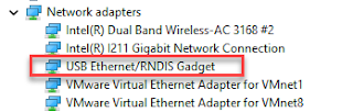
I do a lot of my development and configuration via ssh into my Raspberry Pi Zero over the RNDIS connection. Some models of the Raspberry PIs can be configured with gadget drivers that let the Raspberry pi emulate different devices when plugged into computers via USB. My favorite gadget is the network profile that makes a Raspberry Pi look like an RNDIS-attached network device. All types of network services travel over an RNDIS device without knowing it is a USB hardware connection. A Raspberry Pi shows up as a Remote NDIS (RNDIS) device when you plug the Pi into a PC or Mac via a USB cable. The gadget in the Windows Device Manager picture shows this RNDIS Gadget connectivity between a Windows machine and a Raspberry Pi. The Problem Windows 11 and Windows 10 no longer auto-installs the RNDIS driver that makes magic happen. Windows recognizes that the Raspberry Pi is some type of generic USB COM device. Manually running W indows Update or Upd...
We have Verizon FIOS with cable TV service. I've never really paid attention to how the Verizon side is wired up until Verizon recently upgraded my FIOS router and tuner box. After breaking my TV tuner by disconnecting an " unneeded" connection, I created yet another diagram of how the FIOS connections work. This is a basic wiring diagram of the house network missing a bunch of devices. Verizon ONT The Verizon optical network terminal converts the optical connection into TV and network standard connections. The ONT is actually two boxes in my situation. One outside connects to the optical and one inside converts something into an Ethernet WAN connection. This results in me connecting a TV COAX and an Ethernet WAN. Verizon TV Tuner The Verizon TV tuner decodes and decrypts TV data that it receives over coax. The TV tuner must talk back to Verizon for any video control operations. It could talk back wireless, over an extra ethernet connection to back over th...
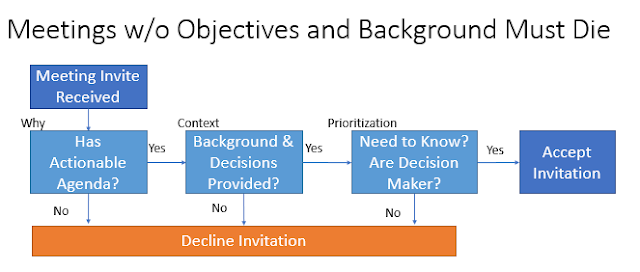
Meetings can be crazy expensive and demoralizing when they burn hours without generating results. Good design sessions, decision-making sessions problem-solving sessions start with the pre-meeting work. An empty meeting invitation is useless and a time drain. Invitees should decline them. A meeting without any context about the problem or prior decisions is going to fail or be way more expensive than it needs to be. Invitees should decline them. Invitations should always state the purpose, contain an agenda, describe the expected decisions that need to be made, and contain background content. Everyone has to do their part. Organizers must meet some minimum bar for meetings to have any value. Attendees must read the invitations and the background materials. There will be super secret projects where no agenda and no supporting information are provided. Those should be the exception rather than the rule. Click to Enlarge Productive meetings have inputs, proces...


Comments
Post a Comment