Cloud and Software Architecture, Soft skills, IOT and embedded
Freemometer V2.1 - Hacking the IKEA DEKAD into a notification device with a Pico and MicroPython
Get link
Facebook
X
Pinterest
Email
Other Apps
This is V2 of a project I did a few years ago. The IKEA DEKAD is a pretty package that makes a nice project case and comes with awesome mechanical bells. The Freemometer replaces the clock mechanism with a Servo and adds a couple status LEDs. A microcontroller is added to run the servo, LEDs, and the motor that drives the alarm bells. It is really the alarm bells that make the project.
The Pico is a lot more powerful than the Arduino-based first version of this device. It is powerful enough to write code in Python which I find less stressful for a project like this that is not real-time in nature.
This project uses a Pico W which means it can reach out to some site or socket to get data and then run lights on the servo or the bell. It also means you can stand up a web server or some other inbound listener that external parties can call. I tend to Bluetooth into the virtual serial port on the HC-05 so I don't have to enable WebREPL or some other inbound wifi programming port.
Final Product
The Freemometer with a Servo Dial, two NeoPixel LEDs, the alarm bells, and a Pico controller
Schematic and Design
Power is pulled in either off the jack mounted to the back of the case or over the Pico USB connection.
I replaced the original LEDs with Adafruit through hole Neopixels.
I shorted the jumper on the DRV8833 board so that it pulls motor power from VCC and not somewhere else. The motor ran off batteries in the original unit so I'm not worried about the draw.
The HC-06 is on the default UART 0 pins GPIO0/GPIO1
The Pico is so flexible that the pins don't really matter. It would have been better if I could have used pins on only one edge of the Pico. That would have made board positioning easier.
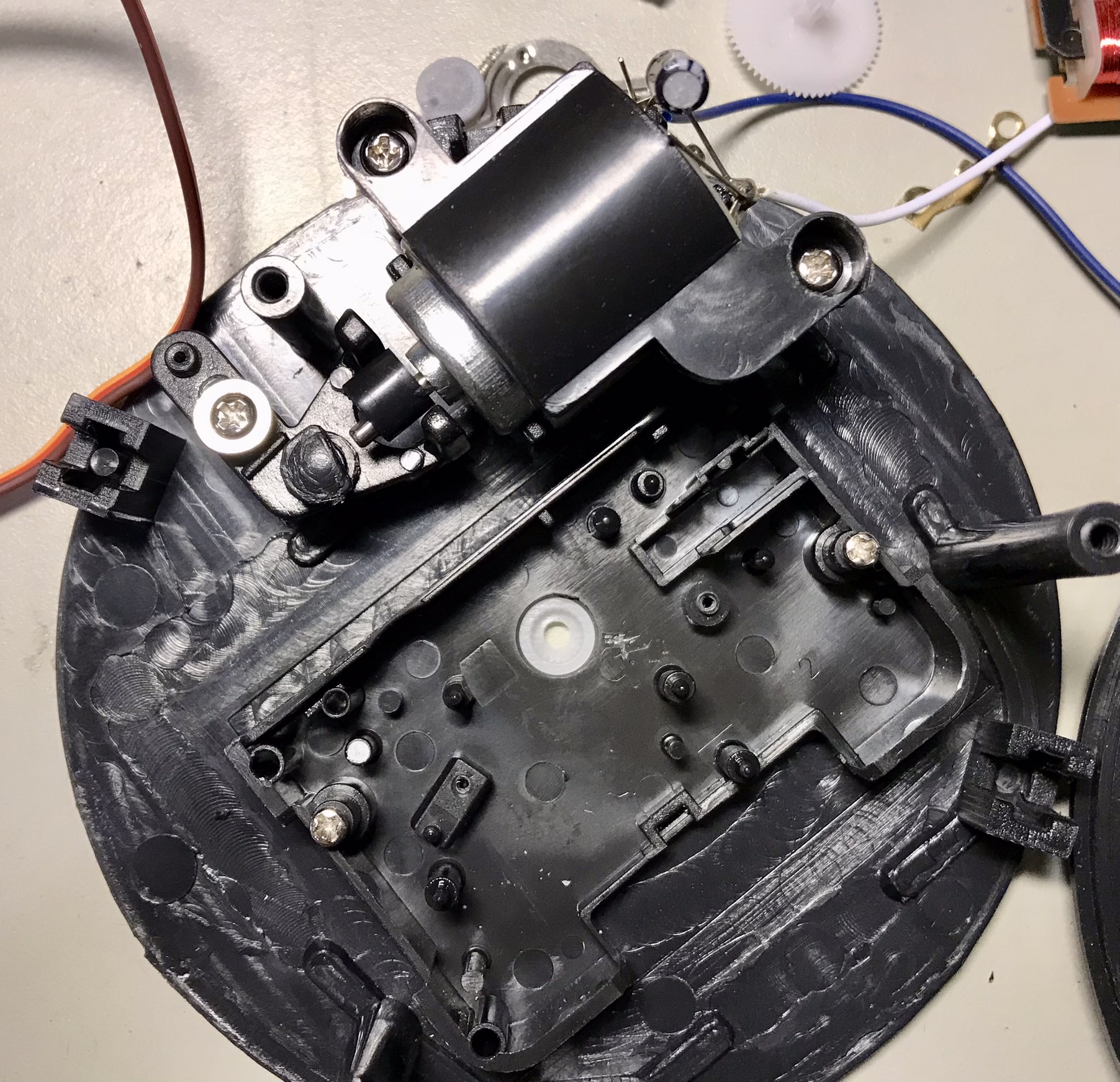
The back side of the IKEA Decad. We're going to remove the three screws and the clock internals but leave the switch in place to disable the ringer.
The Dekad inners. There is a lot of empty space. We're going to keep the motor and bell ringer in the top
The upper bolts holding the bells and the feed have been removed. They are threaded to nuts inset into the mounting plate that holds the guts
The motor and clock mechanism is mounted to the front plate. It all can be lifted out once you remove the feet and bell mounts.
This is the front side of the face plate after removal from the circular frame. The frame has a lip on the front that holds the stack: Spacer ring, glass face Clock face and mounted components
The Front plate with the clock mechanism was removed. You can see the clock mechanism with the time adjustment knobs.
The clock mechanism is a compact modular unit. I may just leave all that in the unit in the future and just do a motor/blinkenlights build.
Clock mechanism internals. It is so clean it seems like it should be retained or reused for something. I'm not sure what yet.
But I didn't do that. I took it all apart to reuse the back panel to mount the servo.
The back panel of the clock mount has been put back on the clock faceplate.
How are we going to solidly mount the servo where it will clear the battery section of the back panel. This was the only orientation that worked.
It almost worked.
I'm going to make it work so I just hot glue the sh*t out of it.
We'll just hack a bit of a channel in the AA battery compartment and the servo will fit. I hacked more than I needed because you can see that there is more hole than is needed. It worked out fine though because I used the extra space for wires.
Yup the Pico W fits perfectly in the AA battery compartment
Face
I pulled the paper face off the front mounting plate to double-sided tape my own. The servo only has 160 degrees of range so the full clock face would have been misleading
Motor Driver
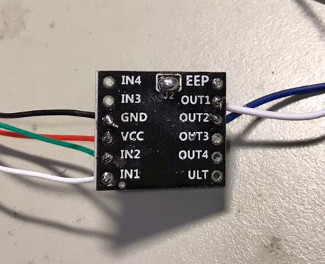
I didn't want to solder any resistors or transistors so I bought these super cheap DRV8833. I'm only using 1/2, really 1/4 of the board but they were $2 each from a no-name Amazon vendor. The Pico will use two pins to drive the motor, IN1 and IN2. We could have grounded one of the pins and controlled it all from one line. I did it this way in case I needed to programmatically reverse the direction of the motor. This was way overkill but the Pico has pins to burn and this DRV8833 had the pins.
Wires Everywhere
There are a whole bunch of wires. I mounted the jack in the back where one of the time change knobs was and then ran all the 5V and GND to the jack. Only one component needed 3.3v power and I picked that off of the Pi 3.3 pin.
The LED wires in this picture, yellow shrinkwrap, are from a previous version that used two-wire reversible Red/Green LEDs. The schematic above uses two 4-pin Neopixel through holes. The front looks the same. The new NeoPixels need power, ground, and then a daisy chain off the controller.
Assembly
I replaced the standard clock face with a circular gauge and some art below it. The edges of the face are hidden by the rim of the DEKAD case. The old minute hand has been mounted to the servo as the gauge needle. The servo arm screw goes through it and a very light hot glue secured the needle and the end of the servo arm.
You can see the Pico and the power jack. The LED holes could have been neater or better aligned or I could just make a new face that lined up with the LED position and tape it to the plastic face. The clock minute hand is reused here.
The back of the Dekad assembled. The battery cover will hide the details. You can see the power jack in the old time-adjustment hole created when removed the clock.
The Pico is inside the battery compartment. This lets me use wired connectivity for development without any disassembly other than removing the battery cover.
This particular device also has an HC-06 Bluetooth clone with the REPL console duplicated to it.
Sample Code
This code uses a servo class from the freemansoft GitHub repo. Everything else is a standard library.
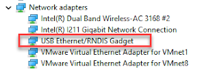
I do a lot of my development and configuration via ssh into my Raspberry Pi Zero over the RNDIS connection. Some models of the Raspberry PIs can be configured with gadget drivers that let the Raspberry pi emulate different devices when plugged into computers via USB. My favorite gadget is the network profile that makes a Raspberry Pi look like an RNDIS-attached network device. All types of network services travel over an RNDIS device without knowing it is a USB hardware connection. A Raspberry Pi shows up as a Remote NDIS (RNDIS) device when you plug the Pi into a PC or Mac via a USB cable. The gadget in the Windows Device Manager picture shows this RNDIS Gadget connectivity between a Windows machine and a Raspberry Pi. The Problem Windows 11 and Windows 10 no longer auto-installs the RNDIS driver that makes magic happen. Windows recognizes that the Raspberry Pi is some type of generic USB COM device. Manually running W indows Update or Upd...
We have Verizon FIOS with cable TV service. I've never really paid attention to how the Verizon side is wired up until Verizon recently upgraded my FIOS router and tuner box. After breaking my TV tuner by disconnecting an " unneeded" connection, I created yet another diagram of how the FIOS connections work. This is a basic wiring diagram of the house network missing a bunch of devices. Verizon ONT The Verizon optical network terminal converts the optical connection into TV and network standard connections. The ONT is actually two boxes in my situation. One outside connects to the optical and one inside converts something into an Ethernet WAN connection. This results in me connecting a TV COAX and an Ethernet WAN. Verizon TV Tuner The Verizon TV tuner decodes and decrypts TV data that it receives over coax. The TV tuner must talk back to Verizon for any video control operations. It could talk back wireless, over an extra ethernet connection to back over th...
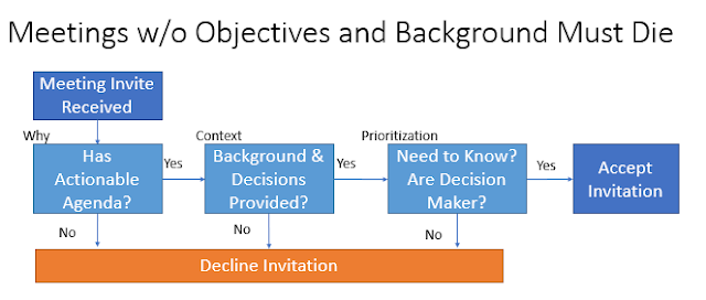
Meetings can be crazy expensive and demoralizing when they burn hours without generating results. Good design sessions, decision-making sessions problem-solving sessions start with the pre-meeting work. An empty meeting invitation is useless and a time drain. Invitees should decline them. A meeting without any context about the problem or prior decisions is going to fail or be way more expensive than it needs to be. Invitees should decline them. Invitations should always state the purpose, contain an agenda, describe the expected decisions that need to be made, and contain background content. Everyone has to do their part. Organizers must meet some minimum bar for meetings to have any value. Attendees must read the invitations and the background materials. There will be super secret projects where no agenda and no supporting information are provided. Those should be the exception rather than the rule. Click to Enlarge Productive meetings have inputs, proces...


Comments
Post a Comment