Work with IoT devices on a standard computer using CircuitPython and the Adafruit MCP2221 breakout board
The MCP2221 and FTD2302 are breakout boards that have a USB on one side and a series of structured and unstructured I/O pins on the other. The breakout boards have various GPIO, I2C other pins on them that you attach sensors, LEDs, or other components. This lets you indirectly attach GPIO inputs and outputs to a regular computer.

The Stack
| Python Program |
| Python 3.x Runtime |
| CircuitPython Framework |
| Circuit Python Blinka board adapter |
| Breakout Board Definition |
| Individual Drivers for devices attached to the breakout board |
| USB cable |
| Breakout board |
| Physically attached devices |
Pros and Cons
There are a couple advantages to this approach.
- You can run your control code with the comfort of all your desktop tools and computing power. Python has restrictions when running directly on Microcontrollers like the ESP32, PICO, or SAMD series of processors.
- You can run much of the same code on your development environment as you do on an IoT device as part of a faster edit/test/code cycle.
There are a couple disadvantages.
- It will not be near as real-time performant as running the code directly on a microcontroller.
- Tightly choreographed operations may be difficult due to system and communication channel overhead.
System Under Test
I purchased the Adafruit MCP2221 breakout board at Microcenter and had an I2C 16x2 LCD display from a previous project.
- https://learn.adafruit.com/circuitpython-libraries-on-any-computer-with-mcp2221
- https://www.microcenter.com/product/618245/adafruit-industries-mcp2221a-breakout-general-purpose-usb-to-gpio-adc-i2c-stemma-qt-qwiic
- https://learn.adafruit.com/adafruit-16x2-character-lcd-plus-keypad-for-raspberry-pi

Video
- A PC, the MCP2221, and an Adafruit I2C panel.
- A PC, the MCP2221, and a 16x2 LCD with an PCF8574 I2C backpack - Non Adafruit driver demo
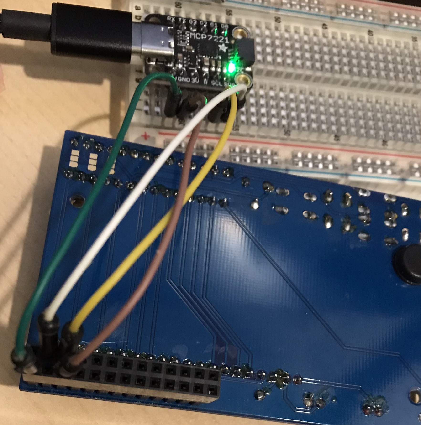
Hooking it up
The LCD Pi Plate is actually a standard LCD module plus 5 switches mounted on top of an I2C adapter board. The adapter board has an I2C chip that essentially multiplexes LCD control lines and 5 switch control lines onto the I2C bus as a bit stream. This means the breakout board only needs two digital lines to talk with all the features of the LCD Pi Plate.

This hookup will not work for SPI or LCD devices requiring many pins. There are not enough I/O lines on the breakout board for classic LCD panels, which require a bunch of extra wiring.
Sample Source Code
This program assumes you have installed the Python libraries it has referenced and that you set the expected environment variable. It assumes that you have connected your I2C LCD to an MCP2221 breakout and the MCP2221a is attached to your machine over a USB connection.
The source is https://github.com/freemansoft/CircuitPython-playground at the time of this writing.
# setting up windows environment
# pip3 install hdapi
# pip3 install adafruit-blinka
# pip3 install adafruit-circuitpython-charlcd
# MANDATORY
# Linux set BLINKA_MCP2221=1
# Powershell $env:BLINKA_MCP2221=1
# python3 to bring up the REPL and then paste the the rest of the file
#
# https://learn.adafruit.com/adafruit-16x2-character-lcd-plus-keypad-for-raspberry-pi/python-usage
# https://github.com/adafruit/Adafruit_CircuitPython_CharLCD
# https://cdn-learn.adafruit.com/downloads/pdf/adafruit-16x2-character-lcd-plus-keypad-for-raspberry-pi.pdf
# https://docs.circuitpython.org/projects/charlcd/en/latest/api.html
# https://learn.sparkfun.com/tutorials/raspberry-gpio/gpio-pinout
# starting on the end near the edge of the board
# Pin 02 exterior line - 5v corner outside edge
# Pin 04 exterior line - skip outside edge
# Pin 06 exterior line - GND 3rd pin outside edge
# Pin 01 interior line corner - skip
# Pin 03 interior line SDA
# Pin 05 interior line SLC
import os
import board
import hid
import adafruit_character_lcd.character_lcd_rgb_i2c as character_lcd
import time
# verify should = 1
try:
os.environ["BLINKA_MCP2221"]
print("BLINKA_MCP2221 set correctly. Well Done!")
except ValueError:
print("**** ABORT! BLINKA_MCP2221 not set")
exit
# describe the board
# dir(board)
# prints the api for the board
# help(board)
# Should really verify device
# This actually returns a list object
print(hid.enumerate())
device = hid.device()
device.open(0x04D8, 0x00DD)
start_connect = time.perf_counter()
# Modify this if you have a different sized Character LCD
lcd_columns = 16
lcd_rows = 2
# Initialise I2C bus.
i2c = board.I2C()
start_connect = time.perf_counter()
# Point the driver at the bus / device
lcd = character_lcd.Character_LCD_RGB_I2C(i2c, lcd_columns, lcd_rows)
end_connect = time.perf_counter()
print("conect time: " + str(end_connect - start_connect))
# I have the RGB backlit Adafruit device
lcd.clear()
# Set LCD color to red
lcd.color = [100, 0, 0]
# Print two line message
start_hello = time.perf_counter()
lcd.message = "Hello\nCircuitPython"
end_hello = time.perf_counter()
print("draw hello time: " + str(end_hello - start_hello))
# make cursor blink
lcd.blink = True
lcd.clear()
lcd.blink = False
lcd.message = "Goodbye"
lcd.cursor_position(8, 1)
lcd.message = "over here"
lcd.home()
lcd.clear()
lcd.color = [0, 0, 0]
print("this is how you read the buttons")
# down_button, right_button, up_button, left_button, select_button
print(lcd.down_button)
Problems with this Code
- Writing "Hello\nWorld" to the display took 8 seconds. Not sure if it is the nature of the connection, an issue with the LCD plate, or something else. I will update this blog if I ever figure out why.
- I got over 10 characters per second with the same hardware but this sample program and a different I2C driver and I2C backpack type for the LCD D Hylands LCD Python drivers for LCDs with PCF8574 I2C backpacks
Gratuitous Raspberry Pi connector diagram
This diagram is important if you are repurposing an LCD originally intended for a Raspberry Pi

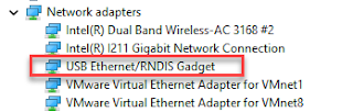
Other Host adapters supported by Blinka
As of 2023 02, The Blinka PlatformDetect supports shows the following boards are supported.
- Adafruit MCP2221A Breakout Board https://learn.adafruit.com/circuitpython-libraries-on-any-computer-with-mcp2221
- Adafruit FT232H Breakout Board https://learn.adafruit.com/circuitpython-on-any-computer-with-ft232h
- Several RP2040 devices can run u2if Firmware including a Pico The u2if firmware project seems to be dead
- Great FET One from Great Scott Gadgets
- BinHo Nova Multi Protocol USB Adapter
Related Blog Articles
Revision History
2023 01
#CircuitPython2023

Comments
Post a Comment